IO602/IO603/IO691 - CAN and LIN Setup
IO602/IO603/IO691 - CAN and LIN Setup — Setup of parameters for CAN,
CAN-FD and LIN channels
Library
Simulink Real-Time - Speedgoat
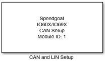
Description
This CAN and LIN Setup driver block is part of the generic block library for the
IO602-2, IO602-4, IO603, and IO691 modules. Your model must contain one CAN and LIN
Setup driver block for each module in your target machine.
The Setup block dialog box allows all of the supported CAN I/O modules (IO602-2,
IO602-4, and IO691) and CAN and LIN I/O modules (IO603) to be configured. It
therefore has an impact on all the other driver blocks (CAN Write, CAN Read or LIN
Write, LIN Read).
Ports
This driver block has no input or output ports.
Parameters
Main Tab
-
Module ID
The Module ID has two functions:
It defines the logical connection between the Setup block
and its I/O blocks
It also informs the auto-search feature of the PCI Slot
parameter. If only one I/O module of this type is installed,
the Module ID must be set to 1. If n modules are installed, it must be in
the range 1:n. Not all the I/O modules installed in the
target machine need to be used.
- Module Type
Select the type of your I/O module installed in your target
machine.
-
PCI Slot (-1: auto-search)
There are two approaches for mapping this block to a specific I/O module installed
in your target machine. All modules of the same type must be configured using the
same method.
Auto-Search: with the default value -1 the I/O module will be automatically located in the
target machine. If you have multiple modules of the same kind, the
Module ID defines which module is associated with this block. To see how
each I/O module maps to a Module ID, use this Speedgoat API:
speedgoat.getIoInterfaces("TargetName", "mySpeedgoat")
Explicit Addressing: to explicitly define the logical address of the
I/O module in the target machine, you can provide the PCI bus and slot
numbers as a vector: [bus, slot]. To determine these numbers, run the
following command in the MATLAB command window:
speedgoat.getIoInterfaces("TargetName", "mySpeedgoat", "Advanced", true)Note
that the PCI address can change whenever an I/O module is added or
removed – usually, auto-search is the best option.
-
CAN Channel Operation Mode Selection
Configuration of the respective protocol mode for each channel. The
available options are:
![[Note]](images/note.png) | Note |
|---|
CAN (HS) according to ISO 11898-2 and CAN-FD according to ISO
11898-1 |
-
LIN Channel Operation Mode Selection
Configuration of the respective mode for each channel. The available
options are:
-
Initialization Structures
Defines CAN messages sent during initialization of the Setup block.
For more information, refer to the usage notes
-
Termination Structures
Defines CAN messages sent during termination of the Setup block. For
more information, refer to the usage notes
-
GPIO Channel Operation Mode Selection
Enabling or disabling of all the GPIO channels. The available options
are:
Channel Setup Tab
The tab for a channel is visible only if the respective channel is enabled in
the Main tab.
-
Nominal Baud Rate
Select the baud rate for CAN (HS) or the arbitration baud rate for
CAN-FD. The options are defined according to the hardware
configuration.
| Note |
|---|
The User defined option should be
used if a baud rate is required that is not configured by default or
if a certain sample point is required. Selecting User defined enables the [BRP, SJW, TSEG1, TSEG2] parameter. Refer
to the usage notes
for more information. |
-
[BRP, SJW, TSEG1, TSEG2]
If the User defined option has been
selected with the Standard Baud Rate
parameter, this parameter is used to configure the bit timing. The
[BRP, SJW, TSEG1, TSEG2] parameter
is a vector with the following elements:
80e6/BRP/(1 + TSEG1 + TSEG2) equals the baud rate.
The ratio between (1 + TSEG1) and (1 + TSEG1 + TSEG2) nominates the
sample point. For additional information refer to can-wiki, info. Use the following settings with respect to
the selected I/O module:
-
Flexible Data Baud Rate
This parameter is only available if the CAN-FD option is chosen within
the Channel parameter. The options are
defined according to the Hardware configuration.
| Note |
|---|
The User defined option should be
used if a baud rate is required that is not configured by default or
if a certain sample point is required. Selecting User defined enables the [BRP, SJW, TSEG1, TSEG2]
parameter. |
-
[BRP, SJW, TSEG1, TSEG2]
The principle is the same as for Nominal Baud
Rate. The BRP of Nominal Baud
Rate and Flexible Data Baud
Rate must be identical for the same channel of the same
I/O module. Failing this, you will get an error notification.
-
120 Ohm Termination Resistor
Enables or disables the internal 120 Ohm termination resistor for this
CAN channel (this feature is currently only
supported for the IO603). For the IO602-2, IO602-4 and
IO691, external termination resistors have to be used to terminate the
bus.
Digital I/O Tab
-
Active Output Channels
Select the active output channels in a vector. A defined number of channels can be
selected using square brackets, for example, [1 2 3]. A sequence of channels can be
selected using a colon, for example, 1:4.
-
Output Voltage [V]
Select the reference voltage of the push-pull output for the front
I/O: 5 V or 3 V.
-
Initial Values
Define the initial signal level present on the outputs after the application has
been downloaded. The values can be set individually by entering a vector: the value
at a certain position in the Initial Values vector
is applied to the channel as defined in the enabled channels. A scalar value applies
to all the channels; for example, for individual values, type "[1 0 0 1]", and to
set all channels to zero, type "0".
-
Reset to Initial Values
Define whether the initial values are also applied once the application has
stopped. The behavior can be set individually for each channel using a vector. A
scalar value applies to all the channels; for example, for individual values, type
"[1 0 0 1]", and to set all channels to zero, type "0". "1" means use the Initial
Value and "0" means keep the latest value.
-
Active Input Channels
Select the active input channels in a vector. Check the active output channels to
avoid conflicts.
-
Input Voltage [V]
Select the reference voltage of the push-, or pull-down resistor for
the front I/O: 5 V or 3.3 V.
-
Pull Resistors - Front connector
Select the reference voltage of the pull resistor for the front I/O:
Pull-up or Pull-down.