IO603 Pin Mapping
IO603 Pin Mapping — Reference information about
the I/O module connector
IO603 Connection Options
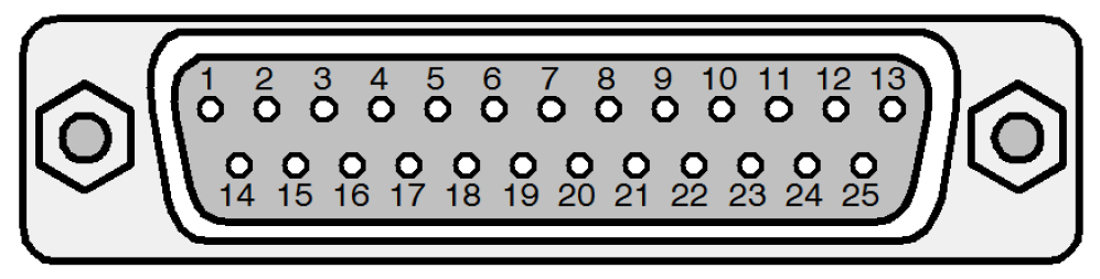
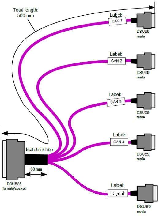
There are two connection options for the IO603 I/O module: the 25-pin onboard
connector and the 25-pin female D-sub to 5x 9-pin male D-sub cable.
CAN I/O Pin Mapping for the 25-Pin D-Sub Onboard Connector:
For proper operation, a CAN topology requires electrical termination in the form
of resistors.
The IO603 I/O module features software-configurable termination resistors.
CAN I/O Pin Mapping for the 25-Pin Female D-Sub to 5x 9-Pin Male D-Sub Cable:
9-pin D-sub connectors for channels 1 and 2 have the following pin mapping:
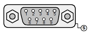
9-pin D-sub connectors for channels 3 and 4 have the following pin mapping:
9-pin D-sub connector for the digital port has the following pin mapping:
For proper operation, a CAN topology requires electrical termination in the form
of resistors.
The IO603 I/O module features software configurable termination resistors.