IO602/IO603/IO691 Usage Notes
IO602/IO603/IO691 Usage Notes — Usage information about the
CAN I/O modules
CAN Message Types
The CAN and CAN FD messages are defined using the CAN_MESSAGE_BUS and
CAN_FD_MESSAGE_BUS Simulink bus datatypes, which contain individual signals for the
different properties of the message. For CAN, a non-bus datatype is available to
support the "SAE J1939" and "XCP over CAN" Simulink blocks. With the exception of
these two use cases, using the non-bus datatype is not recommended.
The CAN_MESSAGE_BUS and the CAN_FD_MESSAGE_BUS datatypes contain the following
signals:
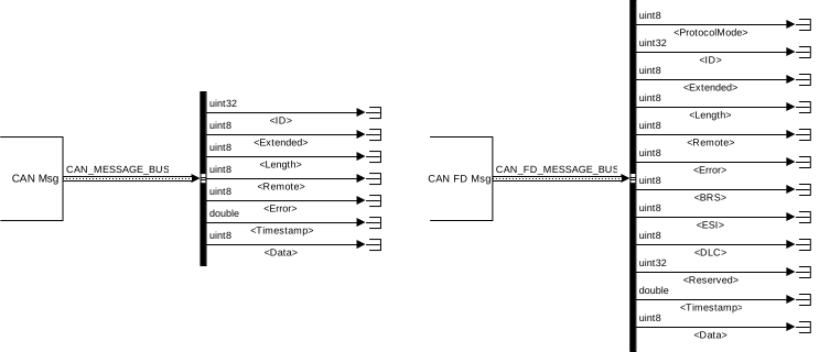
To create a bus object in the base workspace for the Simulink CAN and CAN FD
message bus, refer to the MathWorks VNT documentation for canMessageBusType and canFDMessageBusType.
CAN and CAN FD Message Bus Signals
(* only used with CAN FD messages.)
CAN Read Modes
The CAN Read block can be used in one of two different read modes: Single Read from Buffer (FIFO) and Specify by IDs. This defines how the CAN messages are read from the
bus.
Single Read from Buffer (FIFO)
With Single Read from Buffer (FIFO), all CAN
messages that are available on the specified CAN channel are stored in a message
queue, which is implemented as a First-In-First-Out (FIFO) buffer. In this mode, the
CAN Read block has direct access to this buffer and if there are messages in the
message queue, the Data present outport will be 1.
With every execution of the CAN Read block, one single message is read from the
queue and output on the CAN Msg output port.
To ensure that the complete receive buffer is processed and emptied in one sample
step, the CAN Read block must be executed multiple times until the Data present outport indicates that there are no messages
remaining in the queue. This can be achieved with a do-while subsystem construction,
which will result in multiple iterations of the complete subsystem. Consequently,
every CAN message that has been read from the bus can be processed individually and
the complete buffer is cleared in every sample step.
The maximum number of iterations is set in the While Iterator
block in the Simulink/Ports & Subsystem library. It should be set to match the
number of messages expected within a sample step (maximum number of messages is
2,047, in line with the size of the block's software buffer).
Inside the subsystem, multiple CAN or CAN FD unpack blocks can be directly
connected to the CAN Msg output port. The matching
IDs are then unpacked into the signals of the message and can be routed out of the
subsystem. If multiple messages with the same Message ID are received, only the most
recent messages will appear in the do-while subsystem output.
The sample time of the subsystem is defined by Simulink inheritance rules: If the
subsystem does not have input ports, it will inherit the fundamental sample time of
the model. Alternatively, the sample time of the subsystem can be controlled by
adding an input port, with a connected signal that has a defined sample time. The
sample time must be chosen depending on the bus load in order to avoid buffer
overflow during one sample step.
A limitation of this read mode is that there can only be one CAN Read block per
channel configured with the Single Read from Buffer
(FIFO) mode. Therefore, all CAN messages that are received on this
channel, must be processed inside this subsystem.
Top Level View
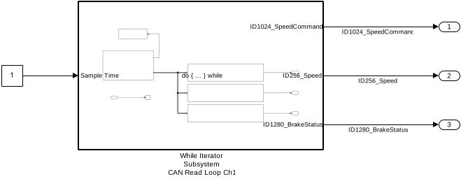
Inside the While Iterator Subsystem
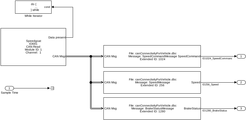
The Sample Time input port defines the rate at
which the subsystem is executed. If the Sample Time
is not defined, the subsystem will run on the base rate.
Specify by IDs
If the application only requires specific CAN IDs and the most recent data of a
CAN message, the Specify by IDs read mode can be
used. In this mode, no While Iterator block is required and the number of CAN Read
blocks per CAN channel is not limited. In this usage mode the role of the
2,047-message deep FIFO is not relevant since only the last received messages are
provided on the ports. When reading the same ID with different CAN Read blocks,
execution with different sample times is supported and all the blocks will read the
most recent CAN messages.
Initialization and Termination CAN Messages
The CAN Setup driver block allows users to define individual CAN messages to be
sent during initialization and termination of the real-time application. This
functionality can be used to initialize or terminate other CAN nodes (such as data
loggers) on the network.
The initialization and termination CAN messages must be defined with structure
arrays that require the following specific field names:
Channel: Selects the CAN channel on which the message is sent.
Protocol: Defines the protocol type of the message to be either CAN or
CAN-FD. The permitted data range is automatically adjusted to [0 8] byte for
CAN or [0 64] byte for CAN-FD.
BRS: Defines whether the fast data baud rate should be used for CAN-FD.
Valid values are either 0 for standard baud rate or 1 for fast data baud
rate (double)
Type: Defines whether the message to be sent is of a standard or extended
type. Valid values are either Standard or
Extended (character vectors)
Identifier: Defines the identifier of the message. The value (scalar) must
be in the corresponding identifier range (standard or extended)
Data: Defines the data frame to be sent out along with the CAN message.
The length of the row vector defines the data frame size. The limits depend
on the selection made for the Protocol
parameter.
Pause: Defines the amount of time, in seconds, that the Setup block waits
after a message has been sent before sending the next message. Valid values
are 0–0.05 seconds. Some CAN nodes need time to settle before they can
accept the next message; for example, the node must settle when the previous
message sets a new operational mode. Use this field to specify the idle
times.
Initialization and Termination Structure
In MATLAB, the following script can be used to create the initialization and
termination structure. The initCAN and termCAN variables must be specified in the
CAN setup block for the Initialization Structures
Array and Termination Structures
Array fields.
% create Initialization structure
initCAN.Channel     = 1;
initCAN.Protocol    = 'CAN-FD';         % 'CAN' or 'CAN-FD'
initCAN.BRS         = 1;                % 0 or 1
initCAN.Type        = 'Standard';       % 'Standard' or 'Extended'
initCAN.Identifier  = 99;               % ID must be double
initCAN.Data        = [8 8 8 8 8 8 8 8];
initCAN.Pause       = 0.05;

% create Termination structure
termCAN.Channel     = 1;
termCAN.Protocol    = 'CAN-FD';         % 'CAN' or 'CAN-FD'
termCAN.BRS         = 1;                % 0 or 1
termCAN.Type        = 'Extended';       % 'Standard' or 'Extended'
termCAN.Identifier  = double(0xFFF);    % ID must be double
termCAN.Data        = [1 1 1 1 1 1 1 1];
termCAN.Pause       = 0.05;
Baud Rate Configuration
The IO602/IO603/IO691 I/O modules offer both pre-defined Baud Rates and custom
configurations.
The CAN driver uses a CAN Controller, which monitors the serial bus line and
performs sampling and adjustment of the sample point by synchronizing with the
start-bit edge and resynchronizing with the following edges.
According to the CAN specification, the nominal bit time is split into four segments:
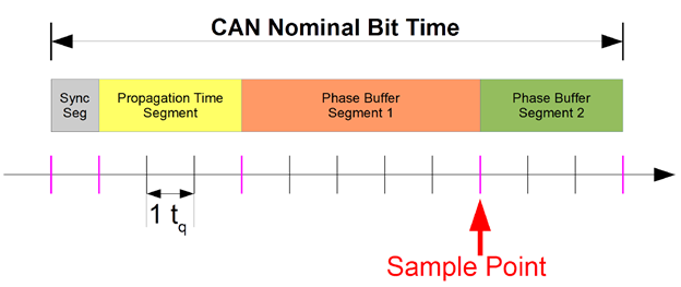
The basic time unit of the CAN Nominal Bit Time is time quantum (tq). The length
of one time quantum is determined by the clock rate of the CAN controller and a Baud
Rate Prescaler. While the synchronization segment has a fixed length, the other
three sections are programmable.
Sync Seg: The Synchronization Segment (Sync Seg) has a fixed length of one
time quantum (1 tq). The edges of the bus level are expected to occur during
the Sync Seg. If an edge occurs outside of Sync Seg, its distance is called
the phase error of this edge. On the other hand, if the edge occurs before
Sync Seg, the phase error is negative.
Prop Seg: The Propagation Time Segment (Prop Seg) compensates for the
physical delay times within the CAN network. These delay times consist of
the signal propagation time on the bus and the internal delay time of the
CAN nodes.
Phase Seg1: The Phase Buffer Segment 1 (Phase Seg1) compensates for
positive phase errors and may be lengthened during resynchronization. The
end of this segment defines the sample point.
Phase Seg2: The Phase Buffer Segment 2 compensates for negative phase
errors and may be shortened during resynchronization.
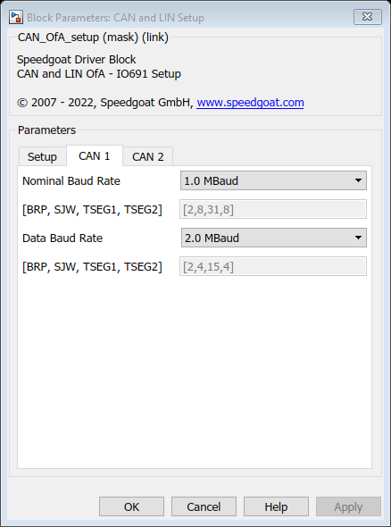
Baud Rate parameters:
BRP: Baud Rate Prescaler (BRP). The bit time quantum (tq) is obtained by
dividing BRP by the CAN controller clock rate (CAN_Clk = 80.000.000 [Hz]).
SJW: Synchronization Jump Width (SJW) value used for the synchronization.
The SJW value must not exceed the time quanta assigned to Phase Buffer
Segment 2. The value of SJW determines by how many tq the Phase Buffer
Segment 1 can be lengthened and subsequently Phase Buffer Segment 2
shortened.
TSEG1: Time segment before the sample point. This covers the Propagation
Time Segment and Phase Buffer Segment 1.
TSEG2: Time segment after the sample point. The minimum value of TSEG2 is
the configured SJW.
The following formulas are used for calculating the CAN bit rate:
tq = BRP / CAN_Clk
t_BS1 = tq * TSEG1
t_BS2 = tq * TSEG2
NominalBitTime = tq + t_BS1 + t_BS2 = tq * (1 + TSEG1 + TSEG2)
CAN Baud rate = 1/NominalBitTime
The sample point (SP) can be adjusted using the relation of TSEG1 and TSEG2. The
default SP for all predefined CAN Baud Rates is at 85%. For CAN FD Baud Rates the SP
is set to 80% by default, unless for 5.0 MBaud where the SP is set to 75%.
Following formula applies to calculate the custom SP:
SP = (1 + TSEG1) / (1 + TSEG1 + TSEG2) = (tq + t_BS1) / NominalBitTime
Depending on the cable length and machine setup, the custom SP can be configured
rather late, for example, 87.5% (recommended value from CiA). For Flexible Data Baud
Rate (FD), you must use the same BRP for both baud rates (Nominal, Data).
Termination Resistors
Termination resistors are crucial components in Controller Area Network (CAN) bus
networks.
Termination resistors are placed at both ends of the CAN bus network, usually near
the physical connectors of the network. Their main purpose is to prevent signal
reflections that can occur when a transmitted signal encounters an impedance
mismatch within the network.
When data is transmitted along the CAN bus, signals can bounce or reflect back
when they reach the end of the bus, especially if the impedance of the bus is not
properly matched. These reflections can interfere with the original signal and cause
errors in data communication.
Termination resistors - typically around 120 Ohm - provide a matched impedance at
both ends of the bus, reducing the likelihood of signal reflections. In summary,
termination resistors are used in CAN bus networks to ensure signal integrity,
prevent reflections, and maintain reliable data communication between various
devices on the network. Proper termination is essential to avoid data corruption and
ensure the overall effectiveness of the CAN bus system.
Some Speedgoat CAN I/O modules feature hardware-configurable or
software-configurable termination resistors, or do not have any termination
resistors at all. It is therefore the responsibility of the user to terminate the
bus according to the bus topology in place.
LIN Message Scheduling
LIN Master nodes manage BUS communication. These nodes will request a response
from any Slave nodes (including the Slave node attached to the Master itself) on the
bus. This request is called a header, and it contains the frame ID to identify which
frame will be sent to the bus.
Each LIN Read and LIN Write block can hold only one ID, and each block configured
as Master can only transmit one header. Consequently, each block configured as Slave
can only respond to the bus with one frame of a specified ID. To ensure only one
header and one successive response are transmitted at a time, and that there is no
conflict on the bus, message scheduling is required at the model level.
The only possible way to achieve this is by placing each LIN Read and LIN Write
block configured as Master into dedicated triggered subsystems.
For example, a pulse generator can be used to initiate a new iteration of the
scheduling process. A delay in between each Master LIN Read or Master LIN Write
block specifies the scheduling of the headers and responses. Each 'n' iteration of
the scheduling process will then follow the same pattern for the duration of the
simulation:
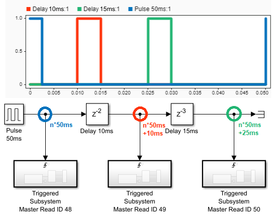
The delay between one subsystem trigger and the following one depends on the frame
size and the configured LIN bit rate. The time a LIN message rests on the bus can be
calculated using the following formula:
t = (1.4 * ((nb * 10) + 44)) / b
Where 'nb' is the number of bits of this specific LIN message, and 'b' is the
configured bit rate in kbit/s. Users are recommended to pad this delay with a
tolerance for jitter.
Usage of LIN Pack and Unpack Blocks
In order to support the Simulink LIN Pack and Unpack blocks, the DLC parameter for
the respective LIN Write and Read block must always be set to 8. Unused data fields
are filled with zero.
When reading LIN messages in a triggered subsystem, as recommended, the output of
the Enable block must be connected to the Msg
Updated input of the LIN Unpack block.
To successfully load a LIN Descriptor File (.ldf), the following requirements must
be met:
The line endings in the .ldf file must conform to the Windows style (CR
LF).
Use the .ldf file of the LIN product example as a template.
Do not rearrange the order of the sections in the .ldf file,
delete them or leave them empty. If necessary, placeholder elements
must be added. In the simplest configuration, only the entries
"Signals", "Frames" and "Signal Encoding Types - physical_value"
have an influence on the functionality of the LIN Pack and Unpack
blocks.
The "physical_value" encoding type is supported for the "Signal Encoding
Types" section but must not be used due to unhandled cases. All other
encoding types are currently not supported and can therefore be used as
placeholders.
The following functions are supported by the LIN Pack and Unpack blocks: