Description
This code module emulates an analog Variable Reluctance Sensor (VRS) output signal
for camshaft or crankshaft position simulation. The code module must be used in
combination with the Crank Angle v4 code module, from which it inherits the high
resolution position signal.
The VRS waveform is stored on the module as an angle-domain lookup table over one
720-degree engine cycle. The lookup table is read out based on the selected shaft
position signal and optional offset. The lookup table contains the normalized
waveform shape only [-1, 1]. Runtime Amplitude, Bias, and optional signal inversion
are applied after the lookup table readout.
In single-table mode, one lookup table with 216 samples
is used. In Multi Tables mode, four independently selectable lookup tables with
214 samples each are available on the module.
Multi-table operation allows runtime switching between different VRS waveform
shapes.
The lookup table can be initialized with a predefined camshaft or crankshaft
waveform template. Alternatively, a custom signal vector can be loaded into the
lookup table. Predefined and custom waveforms are normalized before being loaded to
the module lookup table.
This driver block must be used in combination with an Analog Output block to
enable and parameterize the corresponding analog output channels.
Lookup Table Initialization
The VRS code module is based on an angle-domain lookup table over one 720-degree
engine cycle. In single-table mode, one lookup table with
216 samples is used. In Multi Tables mode, four
independently selectable lookup tables with 214 samples
each are available on the module.
The lookup table contains the normalized waveform shape. The final analog output
voltage is generated by applying runtime signal inversion, Amplitude, and Bias after
the lookup table readout.
Vout = Bias + Amplitude * LUT(mod(Angle + Offset, 720 deg))
Predefined camshaft and crankshaft templates can be used to initialize the lookup
table. As a third option, a custom signal vector can be generated in MATLAB®,
simulation, or from measurement data and loaded to the module lookup table.
Crankshaft
The crankshaft signal is generated based on the number of physical crank teeth per
crankshaft revolution, the index of missing teeth, and the tooth width. Since the
lookup table covers one 720-degree engine cycle, the crankshaft pattern is
represented over two crankshaft revolutions.
The predefined crankshaft waveform is a simplified VRS template. The VRS signal is
approximated by a sine-shaped pulse segment for each tooth such that the leading and
trailing tooth edges are aligned with the positive and negative peaks of the
generated waveform. The tooth width is the relative length of a tooth with respect
to one segment. A tooth width of 0.5 results in a continuous sine wave signal for a
crank pattern without missing teeth.
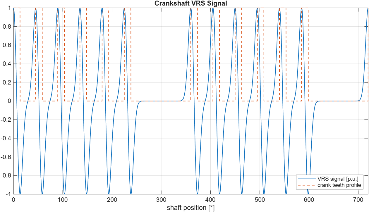
The following graph shows an example of a generated waveform for a crankshaft. The
physical location of the teeth is indicated in orange. The signal is based on the
following parameters:
Number of teeth per revolution, including missing teeth: 8
Missing teeth index vector: [7, 8]
Tooth width: 0.3
Camshaft
The camshaft signal is generated based on the starting angle of each tooth and its
length in degrees. The predefined camshaft waveform is a simplified VRS template.
The VRS signal is approximated by a sine-shaped pulse segment for each tooth such
that the positive and negative edges of the tooth are aligned with the positive and
negative peaks of the generated waveform.
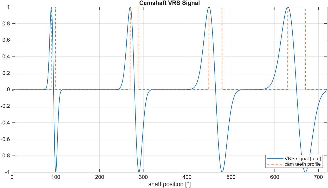
The following graph shows an example of a generated waveform table for a camshaft.
The physical location of the teeth is indicated in orange. This example is based on
the following parameters:
Cam Tooth Start Angle Vector: [90, 270, 450, 630]
Cam Tooth Length Vector: [10, 20, 30, 40]
Custom
The lookup table can also be initialized with a custom waveform generated in
MATLAB, simulation, or from measurement data. The custom waveform must describe one
complete 720-degree engine cycle. The samples are assumed to be uniformly
distributed over the 720-degree cycle.
Custom waveforms are normalized before being loaded to the module lookup table.
Runtime Amplitude, Bias, and optional signal inversion are applied after the lookup
table readout. The custom waveform should be periodic at the 0-to-720 degree
boundary to avoid discontinuities during lookup table wraparound.
In single-table mode, one custom waveform is loaded into a
216 sample lookup table. In Multi Tables mode, one to
four custom waveforms can be loaded into the four 214
sample lookup tables. Unused tables are initialized to zero.
The predefined sine-shaped camshaft and crankshaft templates provide a convenient
synthetic waveform. They do not model speed-dependent VRS amplitude, air-gap
effects, magnetic saturation, sensor loading, or ECU front-end behavior. For
higher-fidelity VRS simulation, use the Custom waveform option and load a waveform
generated from measurement data, magnetic simulation, or an external signal model.
Example MATLAB code for generating one single-table waveform:
% Generate one 2^16-sample waveform over 0 <= theta < 720 degrees.
% Do not duplicate the 720 degree endpoint, because it is identical to 0 degrees.

N = 2^16;
theta = (0:N-1) * 720 / N;

% Example: 10 sine periods per 360 degrees, therefore 20 periods over 720 degrees.
signalVector = sin(deg2rad(10 * theta));
Example MATLAB code for resampling a custom periodic waveform to one
216 sample table:
% waveform contains one complete 720 degree cycle without duplicating the
% 720 degree endpoint.

Nout = 2^16;

thetaIn = (0:numel(waveform)-1) * 720 / numel(waveform);
thetaOut = (0:Nout-1) * 720 / Nout;

% Add a periodic endpoint for interpolation only.
thetaInExt = [thetaIn, 720];
waveformExt = [waveform(:).', waveform(1)];

signalVector = interp1(thetaInExt, waveformExt, thetaOut, 'pchip');
Example MATLAB code for creating a four-table waveform matrix in Multi Tables
mode:
% Create a 4 x 2^14 waveform matrix.
% Each row contains one complete 720 degree waveform.

N = 2^14;

wavetable = zeros(4, N);
wavetable(1, :) = waveform_1_14k(:).';
wavetable(2, :) = waveform_2_14k(:).';
wavetable(3, :) = waveform_3_14k(:).';
wavetable(4, :) = waveform_4_14k(:).';