Cam and Crank Usage Notes
Cam and Crank Usage Notes — Usage information
about the I/O module
Example of crank- and camshaft signals
Important: Crankshaft teeth per revolution includes
all teeth, also the missing tooth/teeth.
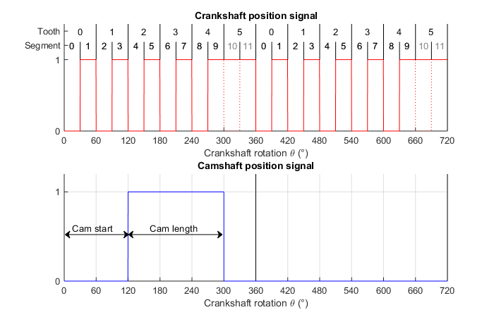
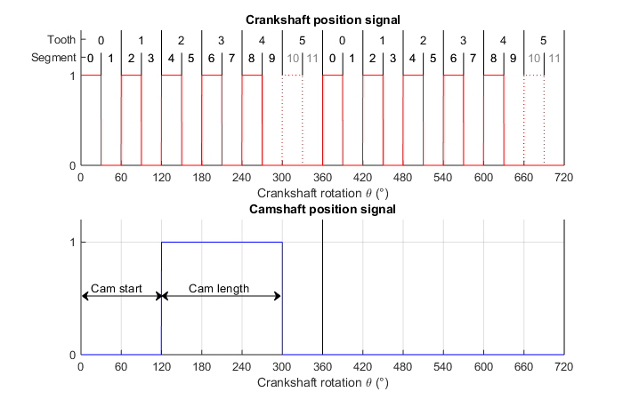
Assuming a crank and a camshaft with the following parameters:
Crankshaft
Camshaft (only one tooth configured)
Cam tooth start: 120°
Cam tooth length: 180°
Depending on the parameter missing tooth signal you get an output signal where the
even segments are high (and the missing tooth low) or the odd segments are high (and
the missing tooth are also high). The segment size theta is 180° divided by
crankshaft teeth per revolution, therefore 30° in this case. This is only true for a
duty cycle of 50%. For other duty cycles, the segment sizes of high and low
segments differ accordingly. Usually various camshafts are connected to one master
crankshaft.
Example of crank- and camshaft encoder signals
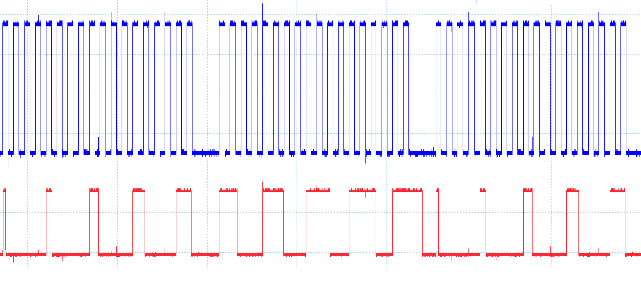
The oscilloscope figure shows the output of a crank encoder (blue) configured with
18 teeth and two missing teeth. The second channel (red) is the output of a cam
encoder with a cam tooth start every 72° and an increasing cam tooth length from
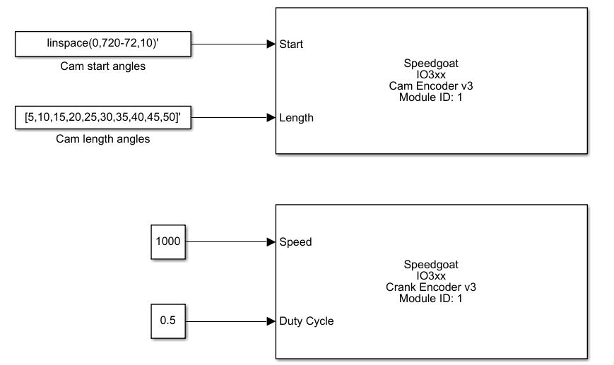
5°-50°. The corresponding Simulink model is shown below.