Cam and Crank - Cam Encoder v3
Cam and Crank - Cam Encoder v3 — The Cam Encoder
generates a binary camshaft signal based on the specified start position and
length of each crank tooth. The module supports up to 10
teeth.
Library
Simulink® Real-Time™ - Speedgoat
Description
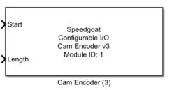
The Cam Encoder generates a binary camshaft signal based on the specified start
position and length of each crank tooth. The module supports up to 10 teeth per
iteration. One iteration is from 0 to 720 degrees. The Cam Encoder module receives
the shaft position signal from a connected Crank Encoder module. The connection of a
Cam Encoder module to a Crank Encoder module is defined in the configuration file
and cannot be changed by the user.
Ports
Inputs
-
Start
Start angle matrix of the maximum 10 cam teeth in degrees [0, 720].
The number of rows of the input matrix must always be 10. The number of
columns of the matrix is equal to the length of the channel vector (as
specified in the dialog mask of this driver). To use less than 10 teeth,
assign value 0 to the Start and
Length inputs.
-
Length
Length angle matrix of the maximum 10 cam teeth in degrees [0, 720].
The number of rows of the input matrix must always be 10. The number of
columns of the matrix is equal to the length of the channel vector (as
specified through the dialog mask of this driver). To use less than 10
teeth, assign value 0 to the Start and
Length inputs.
Parameters
Tab: Module setup
-
Configurable I/O Module ID
This parameter associates a code module block with a configurable I/O module setup
block. Set this value to match the Module ID defined in the setup block of the
required configurable I/O module.
-
Channel Vector
A vector of channels this driver block entity will access. You can specify
channels in the range 1-N (N = the number of channels implemented in your specific
configuration file defined in the Setup block). The width of this vector also
defines the subsequent size of some of the following parameters if scalar expansion
applies. With a single block, all the channels of the block are synchronized.
-
Sample Time
Defines the base sample time at which this driver block gets its sample hit. This
parameter can also be set to -1 for inherited
sample time. The units are in seconds.
Tab: Cam Encoder
-
Initial Cam Start Matrix
This parameter defines the default values of the start angle matrix of
the maximum 10 cam teeth in degrees [0, 720]. The default values are
used initially at model start. The number of rows of the input matrix
must always be 10. The number of columns of the matrix is equal to the
length of the channel vector (as specified through the dialog mask of
this driver). To use less than 10 teeth, assign value 0 to the Start and Length parameters of a cam tooth.
-
Initial Cam Length Matrix
This parameter defines the default cam teeth length matrix in degrees
of the maximum 10 cam teeth [0, 720]. The default values are used
initially at model start. The number of rows of the input matrix must
always be 10. The number of columns of the matrix is equal to the length
of the channel vector (as specified through the dialog mask of this
driver). To use less than 10 teeth, assign value 0 to the Start and Length parameters of a cam tooth.
Tab: Input and Output Ports Configuration
-
Show Cam Start and Length Input Port
This checkbox enables two optional inputs of the driver block allowing
you to alter the cam teeth start angle and cam teeth length during model
execution.