Cam and Crank - Variable Reluctance Sensor v3
Cam and Crank - Variable Reluctance Sensor v3 — This code
module emulates an analog output signal of a Variable Reluctance Sensor (VRS) to
determine the position of a camshaft or crankshaft.
Library
Simulink® Real-Time™ - Speedgoat
Description
This code module can be used independently or as an extension to the Crank Encoder
v3 code module. The module emulates an analog output signal of a Variable Reluctance
Sensor (VRS) to determine the position of a camshaft or crankshaft. The VRS module can
be used independently or in combination with a Crank Encoder v3 code module. In the
latter case, the crankshaft position signal is inherited from the Crank Encoder
module. Multiple VRS code module channels can be used in parallel and share a common
shaft position signal.
The VRS signal waveform is stored in a configurable lookup table on the module.
The lookup table is read out and interpolated based on the shaft position signal.
One iteration is from 0 to 720 degrees. The lookup table contains 2^14 elements. It
can be initialized in the driver block mask. A template for either a camshaft or crankshaft
signal can be used. Alternatively a custom waveform can be loaded into the
lookup table.
This driver block must be used in combination with an Analog Output block to
enable and parameterize the corresponding Analog output channels.
Ports
Inputs
-
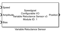
Speed
This input signal defines the engine speed [rpm]. The input is
disabled if the engine position is inherited from a second VRS channel
or a Crank Encoder v3 code module.
-
Amplitude
This input signal defines the amplitude [V] of the analog VRS output
signal. The output signal saturates if the analog output range is
exceeded.
-
Bias
This input signal defines the bias [V] of the analog VRS output
signal. It is limited to the range of the analog outputs of the
configurable I/O module.
Outputs
-
Position
Engine position signal between 0 and 720 degrees. The engine speed is
integrated on the module to compute the position signal at FPGA base
frequency. The position signal is read back by the driver and available
at this output port for further use in Simulink. This output can be
enabled in the mask of the driver block.
Parameters
Tab: Module Setup
-
Configurable I/O Module ID
This parameter associates a code module block with a configurable I/O module setup
block. Set this value to match the Module ID defined in the setup block of the
required configurable I/O module.
-
Channel
The number of the channel which this driver block entity will access.
Only one channel per driver block can be addressed. You can specify
channels in the range 1-N (N = the number of channels implemented in
your specific configuration file defined in the Setup block).
-
Sample Time
Defines the base sample time at which this driver block gets its sample hit. This
parameter can also be set to -1 for inherited
sample time. The units are in seconds.
Tab: VRS
-
Inherit Position Signal From Master
The VRS module inherits the shaft position signal from a Crank Encoder
v3 code module channel or a second VRS code module channel if this
checkbox is selected. Refer to the manual of the configuration file to
learn how the position signal is shared between code modules.
-
Show Position Output
Enable the position output for this driver block instance.
-
Invert Signal
Invert the polarity of the signal waveform.
-
Waveform
Generate a waveform lookup table:
-
Cam Tooth Start Angle Vector
The cam tooth start angle vector defines the starting angle of each
cam tooth in degrees. The range is from 0 to 720 degrees.
-
Cam Tooth Length Vector
The cam tooth length vector defines the length of each cam tooth in
degrees. The vector length must match the number of elements of the cam
tooth start angle vector.
-
Averaging Window Length
A moving average filter can be applied to the generated waveform to
smooth the signal. The width of the averaging window is defined in
degrees. Set the width to zero to disable the averaging filter.
-
Number of Crank Teeth
An integer number of crank teeth between 1 and 180.
-
Missing Teeth Vector
A vector with the indices of the missing crank teeth.
-
Crank Tooth Width
The width of a crank tooth within one segment. The accepted range is
between 0.1 and 0.5.
-
Signal Vector
A vector describing a custom waveform for one iteration between 0 and
720 degrees. The number of elements is not defined. The vector will
automatically be interpolated and scaled to match the lookup table size
and the digital-to-analog converter resolution.
-
Angle Vector
A vector providing the corresponding angle for each element of the
signal vector. The angle vector must cover the range between 0 and 720
degrees and is used for interpolation of the signal vector. The units
are in degrees.
Lookup Table Initialization
The VRS code module is based on a lookup table with 214
entries. The lookup table can be initialized based on predefined patterns for a cam
or crankshaft. As a third option, a custom waveform can be conditioned and loaded
to the lookup table of the VRS code module. For this third option, a signal and
angle vector pair must be provided covering one iteration from zero to 720
degrees.
Crankshaft
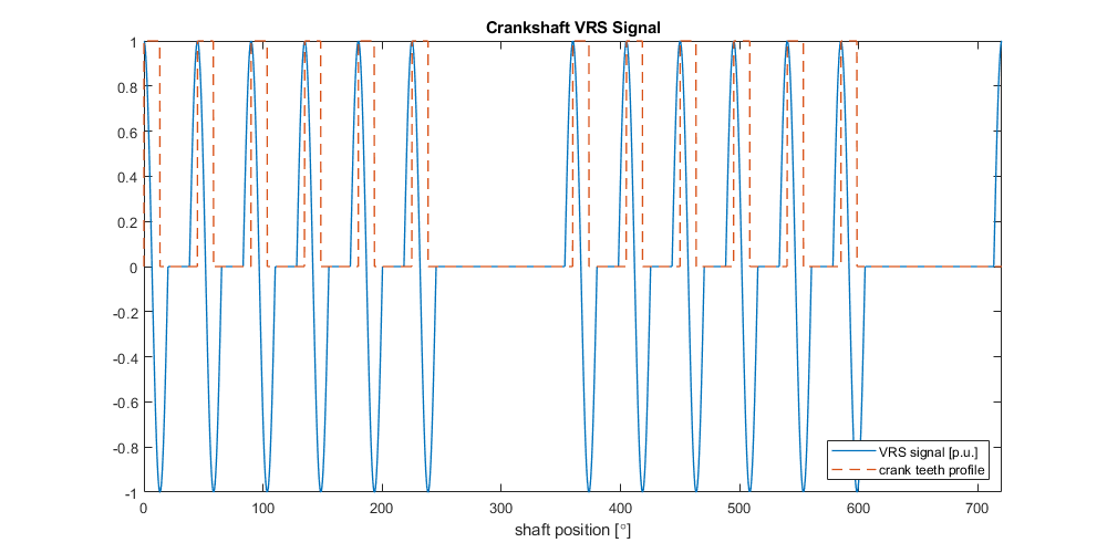
The crankshaft signal is generated based on the number of teeth, index of missing
teeth, and tooth width. The generated lookup table is scaled to make use of the full
resolution of the digital-to-analog converter (16-bit). The VRS signal is
approximated by a sine function for each tooth such that the positive and negative
edge of the tooth are aligned with the positive and negative peak of the sine wave.
The tooth width is the relative length of a tooth with respect to one segment. A
tooth width of 0.5 results in a continuous sine wave signal. The following graph
shows an example of a generated waveform for a crankshaft. The physical location of
the teeth is indicated in orange. The signal is based on the following
parameters:
Camshaft
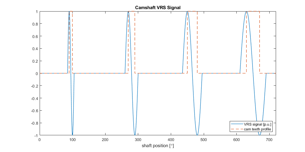
The camshaft signal is generated based on the starting angle of each tooth and
its length in degrees. The generated lookup table is scaled to make use of the full
resolution of the digital-to-analog converter (16-bit). The VRS signal is
approximated by a sine function for each tooth such that the positive and negative
edge of the tooth are aligned with the positive and negative peak of the sine wave.
The following graph shows an example of a generated waveform table for a camshaft.
The physical location of the teeth is indicated in orange. This example is based on
the following parameters:
Cam Tooth Start Angle Vector : [90,270,450, 630]
Cam Tooth Length Vector : [10,20,30,40]
Custom
The lookup table can be initialized based on a custom waveform; for example, a
custom signal can be generated based on a MATLAB® script, simulation or measurement
results. The waveform must be described by a signal vector and corresponding angle
vector; for example, to initialize the lookup table with a sine wave of 20 periods
per 720-degree cycle, the following vectors must be provided: