Cam and Crank - Events Capture v3
Cam and Crank - Events Capture v3 — This Events
Capture code module records the current crank angle (0 to 720°) when an event
pulse is detected.
Library
Simulink® Real-Time™ - Speedgoat
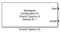
Description
This Events Capture code module records the current crank angle (0 to 720°) when
an event pulse is detected. This Code Module also records the length (in angle) of the
input event.
The driver block provides the last four (4) events captured to Simulink.
Ports
This driver block has up to two (2) output ports:
Outputs
-
Start
Displays the start angle in degrees of the input event.
-
Length
Displays the angle length in degrees of the input event.
Parameters
Tab: Module setup
-
Configurable I/O Module ID
This parameter associates a code module block with a configurable I/O module setup
block. Set this value to match the Module ID defined in the setup block of the
required configurable I/O module.
-
Crank Master Channel:
The corresponding crank encoder master. The crank encoder master is
predefined during the pin layout.
-
Channel Vector
A vector of capture events channels this driver block entity will
access. Channels can be specified in the range 1 to N. The order of
channels can be freely mixed, but the same channel should not be used
more than once. The width of this vector also defines the resulting size
of some of the following parameters if scalar expansion applies. Channel
helps set the output ports dimension. (e.g., if channel vector is set to
[1:12] and event width is set to 4, then the output port is of size
[12x4]). Matrix columns outputs events per channel.
-
Debounce Duration
Defines the time in seconds during which the Events Capture input
signal must be stable before an edge is detected. Defaults to 100e-9
(100 ns).
The range and resolution of the debounce duration depends on the
module frequency configured in the Setup block. The Effective Debounce Duration therefore
indicates the applied duration at the module level.
To disable debouncing, enter the value 0.
Valid values are in the range 0 to 2^8-1 ticks (e.g., 3.413 µs
at a frequency of 75 MHz). The parameter is only visible if
the configuration file supports Events Capture v3.2. The parameter must
be a scalar value which applies to all channels defined in the Channel Vector.
-
Sample Time
Defines the base sample time at which this driver block gets its sample hit. This
parameter can also be set to -1 for inherited
sample time. The units are in seconds.
Tab: Input and output port configuration
-
Events Width
This parameter defines how many events are displayed to Simulink.
Valid values are between 1 and 4. Events width helps set the output
port dimension. (e.g., if channel vector is set to [1:12] and event width
is set to 4, then the output port is of size [12x4]). Matrix rows
outputs events from events(1) to events(Events width), where events(1)
is the most recent captured event and events(Events width) is the
oldest.
-
Show Angle Start Output
When this parameter is checked an additional output is available to
read the start information of the captured events.
-
Show Angle Length Output
When this parameter is checked an additional output is available to
read the length information of the captured events.