Cam and Crank - Events Capture v4
Cam and Crank - Events Capture v4 — The Events
Capture code module records the current crank angle (0 to 720°) when a digital
event pulse is detected. The code module captures the pulse duration in seconds
and degrees and the exact angle when a pulse occurs.
Library
Simulink® Real-Time™ - Speedgoat
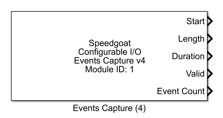
Description
The Events Capture code module records the current crank angle (0 to 720°) when a
digital event pulse is detected. The code module captures the pulse duration in
seconds and degrees and the exact angle when a pulse occurs.
The block must be used in combination with the Crank Angle v4 block from which it
inherits the high-resolution position signal.
Up to two angular windows can be defined in the block mask to suppress incoming
pulses outside of the window of interest.
Ports
Outputs
The output ports of the Events Capture v4 block provide access to signals that
characterize the captured event pulses. The event data is updated at the end of
a window or engine cycle (0°).
If not otherwise noted, the output port dimensions depend on the Number of events (e) and Channel vector (c) parameters defined in the block mask. The
ports output a matrix with dimensions e by c. The output port data type is
double. If windowing is enabled, separate output ports are available per window,
with suffix 1 or 2.
-
Start
The Start output port provides the event start angle in degrees.
-
Stop
The Stop output port provides the event stop angle in degrees.
-
Length
The Length output port provides the length of the event in
degrees.
-
Duration
The Duration output port provides the duration of the event in
seconds.
-
Valid
The Valid output port provides a validity flag (0 or 1) of type double
for the Start, Stop, Length, and Duration outputs. Its dimensions match
these ports. At each index, a value of 1 indicates valid data and a
value of 0 indicates invalid data (e.g., when no pulse is
detected).
-
Event Count
The Event Count port indicates how many events were captured during
the last window or cycle. If windowing is enabled, one Event Count
output port is available per window, with suffix 1 or 2. The port
outputs a vector of type double. The vector length matches the number of
defined channels in the block mask.
-
Error
The Error port signals loss of event data. This can happen when the
execution rate of the CPU block is too low compared to the speed of the
crankshaft. The block should be executed at least once per engine cycle
to transfer all captured events to the CPU.
Parameters
Tab: Module setup
-
Configurable I/O Module ID
This parameter associates a code module block with a configurable I/O module setup
block. Set this value to match the Module ID defined in the setup block of the
required configurable I/O module.
-
Channel Vector
A vector of Event Capture channels that are addressed by this block
entity. Channels can be specified in the range 1 to N but must not exceed
the number of implemented channels in the selected configuration file in
the Setup block. The order
of channels can be freely defined. The same channel must not be used
more than once. The number of channels impacts the expected dimensions
of vector parameters and output port dimensions.
-
Sample Time
Defines the base sample time at which this driver block gets its sample hit. This
parameter can also be set to -1 for inherited
sample time. The units are in seconds.
-
Angle source channel vector
The Events Capture v4 block must be used in combination with the
Crank Angle v4 block,
from which it inherits the position signal. The Angle source channel vector defines from which Crank
Angle v4 channel each Events Capture v4 channel inherits its position
signal. Multiple Events Capture channels can inherit their position
signal from the same Crank Angle channel.
Tab: Event and window configuration
-
Reference angle vector
A reference angle between 0° and 720° can be defined for each active
Events Capture channel. The captured start and stop angles of an event
are output relative to the defined reference angle. For example, if the
reference angle is set to 90° and an incoming pulse is detected at 95°,
the Start output will indicate that the event started at 5°, relative to
the defined reference angle.
The parameter accepts vectors or scalars. If a vector is used, its
length must match the number of active channels of this block. Scalar
inputs apply to all active channels.
-
Number of events
This parameter defines how many events are expected per channel
during one engine cycle. The Number of
events must be identical for all channels defined in one
block. The edit field expects a scalar integer value in the range of 1
to 8. It has a direct impact on the output port dimensions. This
parameter is not visible if windowing is enabled.
-
Events per window
This parameter defines how many events are expected per window and
channel during one engine cycle. The Events per
window must be identical for all channels defined in one
block and also for both windows. The edit field expects a scalar integer
value in the range of 1 to 4. It has a direct impact on the output port
dimensions. This parameter is only visible if windowing is
enabled.
-
Enable window 1
This parameter defines whether windowing is active or not. When this
checkbox is empty, all incoming pulses are considered. When the checkbox
is enabled, only pulses that occur within the defined window are
considered. All other pulses are ignored. Pulses that cross the window
boundaries are truncated.
-
Window 1 start angle vector
This parameter defines the angle at which the window starts. The
window boundaries can be defined for each channel relative to the
Reference angle vector of the
channel. The parameter must be either a scalar or a vector with the same
length as the Channel vector.
-
Window 1 stop angle vector
This parameter defines the angle at which the window stops. The window
boundaries can be defined for each channel relative to the Reference
angle of the channel. The parameter must be either a scalar or a vector
with the same length as the Channel
vector.
-
Enable window 2
This checkbox defines whether a second window is active or not. Note
that window 2 can only be enabled if window 1 is already enabled; otherwise, this parameter is not visible.
-
Window 2 start angle vector
This parameter defines the angle at which the window starts. The
window boundaries can be defined for each channel relative to the
Reference angle of the channel. The parameter must be either a scalar or
a vector with the same length as the Channel
vector.
-
Window 2 stop angle vector
This parameter defines the angle at which the window stops. The window
boundaries can be defined for each channel relative to the Reference
angle of the channel. The parameter must be either a scalar or a vector
with the same length as the Channel
vector.
Tab: Output port configuration
-
Show start angle output
Enable the Start output port. If windows are enabled, the block has
one start output port per window.
-
Show stop angle output
Enable the Stop output port. If windows are enabled, the block has one
stop angle output port per window.
-
Show length output
Enable the Length output port. If windows are enabled, the block has
one length output port per window.
-
Show duration output
Enable the Duration output port. If windows are enabled, the block has
one duration output port per window.
-
Show valid output
Enable the Valid output port. If windows are enabled, the block has
one valid output port per window.
-
Show event count output
Enable the Event Count output port. If windows are enabled, the block
has one event count output port per window.
-
Show error output
Enable the Error output port.
Tab: Digital input configuration
-
Debounce Duration
Defines the time in seconds during which the Events Capture input
signal must be stable before an edge is detected. Defaults to 100e-9
(100 ns).
The range and resolution of the debounce duration depends on the clock
frequency defined in the configuration file. The Effective Debounce Duration therefore indicates the
applied duration at the module level.
To disable debouncing, enter the value 0.
Valid values are in the range 0 to 2^8-1 ticks (e.g., 2.55 µs
at a frequency of 100 MHz). The parameter must be a scalar
value which applies to all channels defined in the Channel Vector.