Cam and Crank - Knock Generator v3
Cam and Crank - Knock Generator v3 — This Knock
Generator code module is an extension to the Crank Encoder v3 code module. It
generates a knock signal at the analog output of the configurable I/O module
once per 720° iteration of the crankshaft.
Library
Simulink® Real-Time™ - Speedgoat
Description
This Knock Generator code module receives the crankshaft angle from the
corresponding Crank Encoder v3 code module channel. A knock pulse is generated once
per 720° iteration. The knock pulse waveform is a cosine with exponential decay.

This driver block must be used in combination with a Crank Encoder v3 block as
well as an Analog Output block to enable and parameterize the corresponding Crank
encoder and Analog output channels.
Ports
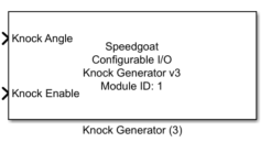
This driver block has two input ports:
Inputs
-
Knock Angle
Defines the angle between 0 and 720° at which the knock pulse occurs.
-
Knock Enable
A signal level 1 at this input enables the knock pulse. The pulse is
disabled with a 0 at this input.
Parameters
Tab: Module setup
-
Configurable I/O Module ID
This parameter associates a code module block with a configurable I/O module setup
block. Set this value to match the Module ID defined in the setup block of the
required configurable I/O module.
-
Channel Vector
A vector of Knock Generator channels this driver block entity will
access. Channels can be specified in the range 1 to N (N is the number
of crank encoder channels in the configuration file). The order of
channels can be freely mixed, but the same channel should not be used
more than once. The width of this vector also defines the resulting size
of some of the following parameters if scalar expansion applies. The
length of the channel vector defines the dimension of the input signals.
-
Sample Time
Defines the base sample time at which this driver block gets its sample hit. This
parameter can also be set to -1 for inherited
sample time. The units are in seconds.
Tab: Knock Generator
-
Amplitude
This parameter defines the amplitude [V] of the knock signal
oscillation. It can be a scalar or vector. The vector length must match
the number of enabled channels.
-
Frequency
This parameter defines the frequency [Hz] of the knock signal
oscillation. It can be a scalar or vector. The vector length must match
the number of enabled channels.
-
Time Constant
This parameter defines the time constant [s] of the exponential decay
of the knock signal. It can be a scalar or vector. The vector length
must match the number of enabled channels.