Cam and Crank - Crank Decoder v1
Cam and Crank - Crank Decoder v1 — The crank decoder
acquires a crankshaft signal (generated from a crank encoder) and a camshaft
signal (generated from a cam encoder) and decodes position (0° - 720°), speed,
etc., based on a predefined crankshaft pattern and a camshaft
tooth.
Library
Simulink® Real-Time™ - Speedgoat
Description
The crank decoder acquires a crankshaft signal (generated from a crank encoder)
and a camshaft signal (generated from a cam encoder) and decodes position (0° -
720°), speed, etc., based on a predefined crankshaft pattern and a camshaft
tooth.
The current implementation of this decoder supports cam profiles which meet the
following conditions:
Only one cam tooth
The start and stop angles of the cam tooth coincide with the start
angle of a crank tooth. For example, for a crank profile with 18 teeth,
of which 2 are missing, the possible cam start and stop angles are
multiples of 360/18 = 20 degrees.
Ports
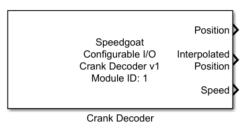
This driver block has no input, and up to five output ports:
Outputs
-
Round
Displays the round information indicating the revolution number within
the two revolution cycle.
Round 1: 0° - 360°
Round 2: 360° - 720°
-
Position
Displays the position with tooth resolution.
-
Speed
Displays the calculated speed.
-
Interpolated Position
The interpolated position between two teeth assumes a constant speed,
calculated from the average of the last four teeth speeds.
-
Synchronization status
0: No crank and no cam signal detected.
1: Crank signal detected, searching for missing teeth.
2: Crank signal synchronized, waiting for cam signal.
3: Rising edge cam signal detected (at expected round). Waiting for
falling egde cam signal.
4: Crank and cam signal synchronized.
Parameters
Tab: Module setup
-
Configurable I/O Module ID
This parameter associates a code module block with a configurable I/O module setup
block. Set this value to match the Module ID defined in the setup block of the
required configurable I/O module.
-
Channel Vector
A vector of channels this driver block entity will access. You can specify
channels in the range 1-N (N = the number of channels implemented in your specific
configuration file defined in the Setup block). The width of this vector also
defines the subsequent size of some of the following parameters if scalar expansion
applies. With a single block, all the channels of the block are synchronized.
-
Sample Time
Defines the base sample time at which this driver block gets its sample hit. This
parameter can also be set to -1 for inherited
sample time. The units are in seconds.
Tab: Crank Decoder
-
Number of teeth vector:
This parameter defines the number of teeth of the crankshaft. Note
that the number of teeth also includes the missing tooth/teeth.
-
Number of missing tooth/teeth vector:
This parameter defines the number of missing tooth/teeth of the crank
shaft.
-
Missing tooth/teeth signal high:
This checkbox defines the level during a segment of the crank signal.
When the checkbox is not checked the even segments are high (and the
missing tooth low) whereas when the box is checked the odd segments are
high (and the missing tooth is also high).
-
Cam tooth offset vector (deg):
This parameter defines the offset (starting point) of the camshaft
pattern in degree. This angle has to coincide with a crank tooth start
angle. e.g., for a crank profile with 18 teeth and 2 missing teeth,
possible cam tooth offset angles are multiples of 360/18 = 20 degrees.
-
Cam tooth size vector (deg):
This parameter defines the size (length) of the camshaft pattern in
degree. The Cam tooth stop angle has to coincide with a crank tooth
start angle. Thus for a crank profile with 18 teeth and 2 missing teeth,
possible cam tooth offset angles are multiples of 360/18 = 20 degrees.
-
Top dead center position vector (deg):
This parameter specifies the top dead center (TDC) position between 0°
and 720°. The units are in degrees (°). This angle has to coincide with
a crank tooth start angle. e.g., for a crank profile with 18 teeth and 2
missing teeth, possible dead center position angles are multiples of
360/18 = 20 degrees.
-
Top dead center pulse duration vector (s):
This parameter defines the duration of the top dead center pulse in
seconds.
-
Start pulse duration vector (s):
This parameter defines the duration of the start pulse in seconds.
![[Note]](images/note.png) | Note |
|---|
Note: values expressed in seconds will be rounded to the FPGA resolution. For
instance, if FPGA base clock is equal to 75[MHz], then the resolution is
13.33[ns]. |
Tab: Output ports configuration
-
Show round
Enables round output port.
-
Show position
Enables position output port.
-
Show speed
Enables speed output port.
-
Show interpolated position
Enables interpolated position output port. The interpolated position
between two teeth assumes a constant speed, calculated from the average
of the last four teeth speeds.
-
Show synchronization status
Enables synchronization status output port.