IO61X - CAN Status
IO61X - CAN Status — This block provides CAN or CAN-FD bus and controller status
information for the configured channel of the IO61X I/O modules
Library
Simulink Real-Time - Speedgoat
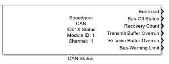
Description
This CAN Status driver block is part of the generic block library for the IO610,
IO611, IO612, IO613 and IO614 I/O modules.
This block provides CAN bus and controller status information for the configured
channel. An optional input port makes it possible to disable this channel. This can
be used to recover from faulty situations like Bus-Off.
Ports
Inputs
-
Disable CAN Channel
This input port is available whenever the Show
Input Port to Disable the CAN Channel checkbox in the
block mask is selected. Use this port to check whether the channel is
enabled to interact on the bus or not.
Providing a logical "1" to this input signal stops the CAN channel
from interacting on the bus. This channel will stop transmission and
reception of new data with the next sample step. The transmit and
receive buffer will be flushed.
This functionality can be used to simulate a channel disconnecting
from the bus. Among other things, this means that the channel stops
setting ACK bits. However, all the status indicators or counter values
will remain until the channel is enabled again.
When the channel is in Bus-Off mode, the state can be recovered using
this input port.
The channel will always start in an enabled state.
Outputs
-
Bus Load
CAN bus load in percentage of the nominal occupation within the sample
time of the Status block. If using a low sample time, the value can
fluctuate significantly.
When the bus is overloaded or a cable is disconnected the signal may
fluctuate between 0% and 100%.
-
Bus-Off Status
Indicates if the CAN controller is in bus off mode as described within
the CAN specification. This is set if either the internal CAN receive
error counter or the CAN transmit error counter reaches the bus off
limit of 255 errors.
This state can be recovered using the Disable
CAN Channel input port.
-
Recovery Count
Number of bus recoveries performed since simulation start. This
counter will only reset at model restart.
-
Transmit Buffer Overrun
Indicates an overrun on the transmit buffer of this channel. This
shows if there was a potential data loss in the output signal flow. The
buffer may overflow if the traffic on the CAN Write block is too large
for the configured sample rate. The size of this buffer is 564
messages.
-
Receive Buffer Overrun
Indicates an overrun on the receive buffer of this channel. This shows
if there was a potential data loss in the output signal flow. The buffer
is only used if the CAN Read block is in FIFO mode. It may overflow if
the bus-load is too high or because the receive buffer is not read out
by a CAN Read block using a fast enough sample rate. The size of this
buffer is 564 messages.
-
Bus-Warning Limit
Indicates if the CAN controller has reached the bus warning limit as
described within the CAN specification. This is set if either the
internal CAN Receive Error Counter or
the CAN Transmit Error Counter reaches
the warning limit of 96 errors.
Parameters
-
Module ID
This ID defines the link to the corresponding Setup block
-
Channel Number
Selects the CAN channel with which this driver block communicates.
-
Automatic Recovery at Bus-Off
Check this parameter in order to enable the automatic Bus-Off
Recovery.
If the channel is in Bus-Off state, as indicated by the Bus-Off Status output port, the channel will
automatically try and recover from this state.
-
Show Input Port to Disable the CAN Channel
Enables an input port that can be used to disable the associated
channel.
-
Sample Time
Defines the base sample time at which this driver block gets its sample hit. This
parameter can also be set to -1 for inherited
sample time. The units are in seconds.
![[Note]](images/note.png) | Note |
|---|
Users are recommended to set the sample time to 100 ms when working with
the Bus-Off Status output. The combination
of setting the sample time below this value, and using a low bit rate value
that slows down the bus recovery process, may lead to incorrect Bus-Off
indications. |