IO610 Pin Mapping
IO610 Pin Mapping — Reference information about
the I/O module connector
Description
The IO610 I/O module offers two DB9 connectors. Each connector contains a CAN
channel.
Channel Location
When plugged into a Speedgoat Performance target machine, the channels are
ordered as shown below:
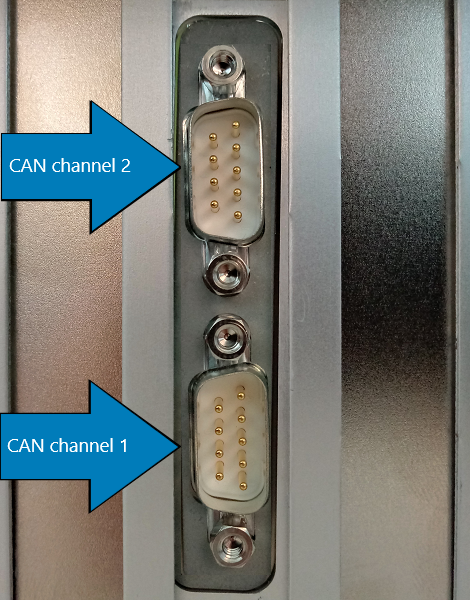
For other machines, please refer to the orientation of the DB9 connectors.
Connector Pin Mapping
The following figure shows the pin numbering of a DB9 connector when looking from
the front (outside of the target machine).
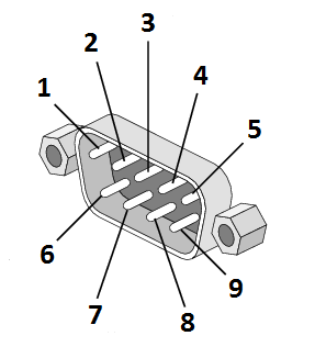
The pin mapping of the two connectors is identical and is listed in the following
table:
For proper operation, a CAN topology requires electrical termination in the form
of resistors.
The IO610 I/O module does not include termination resistors. The full resistor
comes with the CAN module loopback cable provided by Speedgoat.