IO613 Pin Mapping
IO613 Pin Mapping — Reference information about
the I/O module connector
Description
The IO613 I/O module offers two DB9 connectors. Each connector contains a CAN
channel.
Channel Location
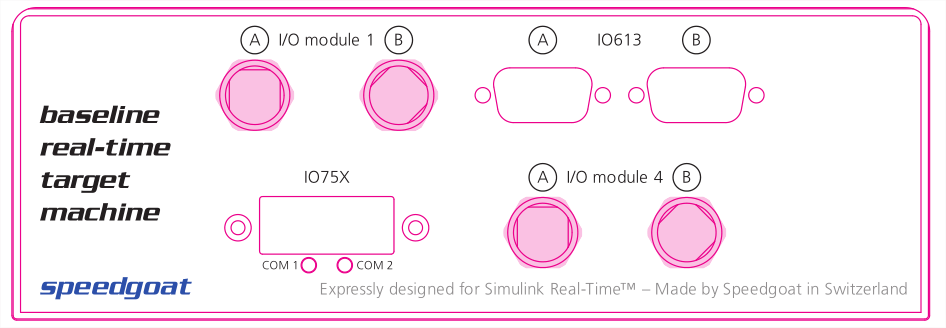
The following figure shows the outlines of an example Baseline target machine
with the IO613 I/O module located in the top-right corner.
![[Note]](images/note.png) | Note |
|---|
Note that the two DB9 connectors are labeled A & B. |
Connector Pin Mapping
The following figure shows the pin numbering of a DB9 connector when looking from
the front (outside of the target machine).
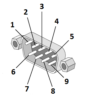
The pin mapping of the two connectors is identical and is listed in the following
table:
For proper operation, a CAN topology requires electrical termination in the form
of resistors.
The IO613 I/O module does not include termination resistors. The full resistor
comes with the CAN module loopback cable provided by Speedgoat.
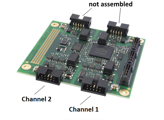
Raw Module
In rare cases, when the IO613 I/O module is used on a different target machine
than the Baseline, the channels can be placed individually using boxed-header-to-DB9
adapter cables.
The channels on the module are ordered as shown in the following picture: