IO611 Pin Mapping
IO611 Pin Mapping — Reference information about
the I/O module connector
Description
The IO611 I/O module offers two DB9 connectors. Each connector contains a CAN
channel and a LIN channel.
Within this context, the LIN channels are named channel 1 and 2.
Channel Location
The LIN channels are paired with the CAN channels as follows:
When plugged into a Speedgoat Performance target machine, the channels are
ordered as shown below:
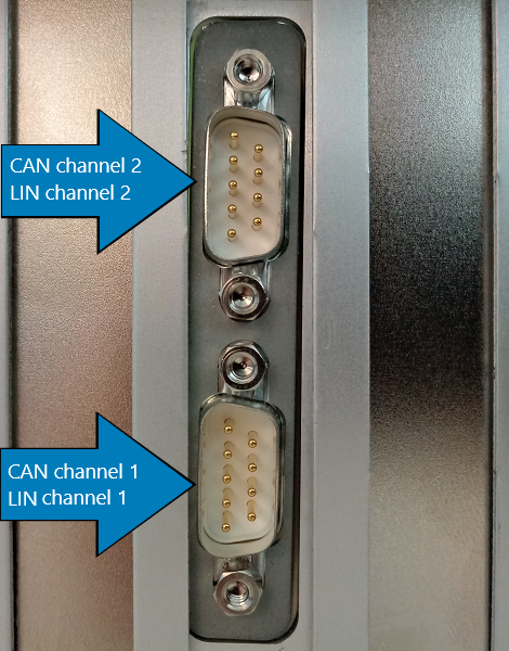
For other machines, please refer to the orientation of the DB9 connectors.
![[Caution]](images/caution.png) | Caution |
|---|
For the Legacy driver blocks, the LIN channels are named channel 3 and 4. |
Connector Pin Mapping
The following figure shows the pin numbering of a DB9 connector when looking from
the front (outside of the target machine).
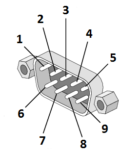
The pin mapping of the two connectors is identical and is listed in the following
table:
For proper operation, a CAN topology requires electrical termination in the form
of resistors.
The IO611 I/O module does not include termination resistors. The full resistor
comes with the CAN module loopback cable provided by Speedgoat.
CAN LS Switch
The adapter provided routes the CAN LS signals to the same pins as CAN HS/FD. This
means that the same cables can be used for CAN HS/FD and CAN LS operation. The CAN
LS switch can be provided on request.