Back to Homepage
Contact Us
Customer Portal
Documentation
Solutions
Products & Services
Knowledge Center
Success Stories
Company
Documentation
CONTENTS
Speedgoat I/O Blockset
I/O Connectivity
Battery Emulation
BMTS
BCE Pin Mapping
FIU Pin Mapping
TSE Pin Mapping
BCE Usage Notes
FIU Usage Notes
TSE Usage Notes
Firmware Update Instructions
BMTS Setup
BMTS Read
BMTS Write
BMTS Bus Pack
BCE AC SM Parameter Update
BMTS Examples
https://www.speedgoat.com/help/slrt/page/icon_documentation.jpg
v10.0.1.x
for R2026a
View other versions
FIU Pin Mapping
FIU Pin Mapping —
Reference information about the I/O module connectors
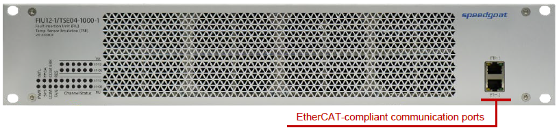
Communication
Port
Description
ETH1
EtherCAT in: connect to the target machine or the previous device of the chain
ETH2
EtherCAT out: connect to the next device of the chain
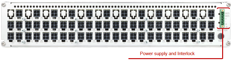
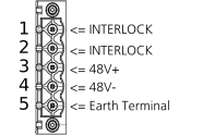
Power Supply and Interlock
Pin
Description
1
Interlock: connect, e.g., to a rack door switch
2
Interlock: connect, e.g., to a rack door switch
3
48 V+: connect to power supply unit
4
48 V-: connect to power supply unit
5
Earth Terminal: must be connected to the protective earth (PE)
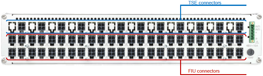
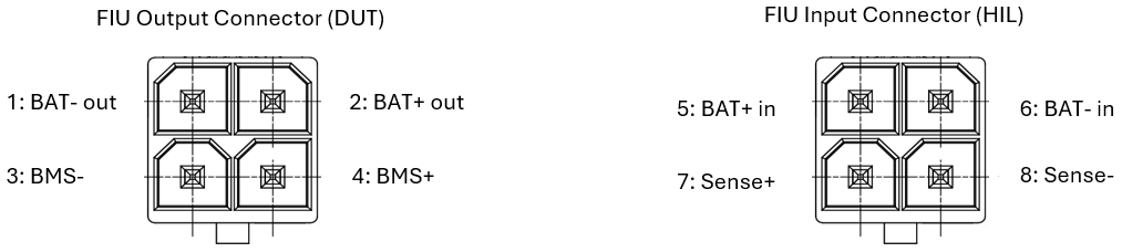
FIU Connectors
Pin
Description
1
BAT- out: Negative fault insertion output pin for cell voltage which can be used to connect cells in series.
2
BAT+ out: Positive fault insertion output pin for cell voltage which can be used to connect cells in series.
3
BMS-: Negative fault insertion output pin for cell voltage which can be used to connect to the CMU of a BMS (Device Under Test).
4
BMS+: Positive fault insertion output pin for cell voltage which can be used to connect to the CMU of a BMS (Device Under Test).
5
BAT+ in: Positive fault insertion input pin for cell voltage. Connect to the BCE.
6
BAT- in: Negative fault insertion input pin for cell voltage. Connect to the BCE.
7
Sense+: Positive fault insertion input pin for the sensing line. Connect to the BCE.
8
Sense-: Negative fault insertion input pin for the sensing line. Connect to the BCE.
×
WeChat