BCE AC Signal Modulation Parameter Update
BCE AC Signal Modulation Parameter Update — Update the AC signal modulation
parameters of the BCE at runtime
Library
Simulink Real-Time - Speedgoat
Description
![[Note]](images/note.png) | Note |
|---|
This documentation refers to the Speedgoat Battery Management Testing Systems
(BMTS) that are supported with MATLAB R2022a and
later. |
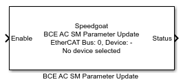
The BCE AC SM Parameter Update block allows the user to update the AC Signal
Modulation parameters of a battery cell emulator (BCE) while the simulation is
running on the real-time target machine.
The AC signal modulation data file can only be changed in the BMTS Setup block and
requires re-compilation of the model. Parameters such as the AC Signal Modulation Time Step, Start Time
Delay, and Gain Adjustment Value for
each cell can be updated on the fly using this block.
It is best to stop the AC signal modulation output before updating the
parameters.
This block is backward compatible with BCE firmware versions up to 1.1.2.0.
Please note that for parameter updates on these firmware versions, AC signal
modulation is paused and the transfer of new parameters is slow.
To enable parameter updates (without stopping the AC signal modulation output),
and faster data transfer, a BCE firmware update to version 1.1.3.0 or later is
required.
Ports
This driver block has one input and one output port.
Inputs
-
Enable
When the Enable signal is 0, the block is disabled. Set the Enable
signal to 1 to start transferring the new AC signal modulation
parameters. The Status output indicates when the transfer is
done.
Data Type:
boolean
Outputs
-
Status
The Status port outputs a boolean signal indicating when the updated
parameters have been transferred to the BCE. After enabling the block,
the Status switches from 0 to 1 when the data transfer is
completed.
Data Type:
boolean
Parameters
EtherCAT Network Parameters
-
EtherCAT Network Index
The EtherCAT Network Index is a user-defined ID to associate the BCE
AC SM Parameter Update block with the corresponding BMTS Setup block.
The value must be an integer between 0 and 11.
-
EtherCAT Device
Selects the BCE device to which the BCE AC SM Parameter Update block
will send data.
-
Sample Time
Defines the base sample time at which this driver block gets its
sample hit. This parameter can also be set to -1 for inherited sample
time. The units are in seconds.
Configuration
BCE AC Signal Modulation Parameters
-
Cell-Specific AC Signal Modulation Settings
Select a cell from the list on the left-hand side to configure
additional settings for this cell.
-
Time Step
Set the time step after which the AC signal modulation outputs the
next sample from the signal data array. The unit can be set to
milliseconds or microseconds. The minimum value is 7 μs.
-
Output Path
Select whether the AC signal modulation data is applied to the cell voltage
or to the cell sink current.
-
Start Time Delay
Add an AC signal modulation start time delay for this cell. To achieve
exact synchronization or time offsets between cells, the AC signal must
be started simultaneously for all cells from Simulink. Each cell will
start AC data output after its start time delay has passed.
-
Stop after X Passes Through the Data File
To stop AC signal modulation deterministically after a certain number
of iterations, enter the number of passes through the data file after
which to stop AC signal modulation. When stopped, the cell returns to
normal operation mode.
-
Gain Adjustment Value
Add an additional gain factor to apply to the data points from the AC
signal data file. The gain value must be in the range of 0 to 2.0.
Setting it to 1 disables the gain adjustment.
-
Gain Sweep Mode
This mode allows the gain value applied to the AC signal modulation
data to change periodically. When enabled, the gain adjustment is
updated each time the number of entered time steps have elapsed. The
current gain adjustment value defines the starting point (1 if
disabled); the gain sweep limit value defines the endpoint. Counting
occurs between these two boundaries. If one boundary is reached, the
counting direction reverses. The current gain value is adjusted
(increased or decreased) by the update step value.
-
Timer Sweep Mode
This mode allows the AC signal modulation output update time step (or
frequency) to change periodically. When enabled, the time step is
updated each time the number of entered time steps have elapsed. The
current time step value defines the starting point; the timer sweep
limit value defines the endpoint. Counting occurs between these two
boundaries. If one boundary is reached, the counting direction reverses.
The current timer value is adjusted (increased or decreased) by the
update step value.