BMTS Firmware Update Instructions
BMTS Firmware Update Instructions — Instructions on how to update
the firmware of BCE, FIU and TSE devices
Overview
![[Note]](images/note.png) | Note |
|---|
This documentation refers to the Speedgoat Battery Management Testing Systems
(BMTS) that are supported with MATLAB R2022a and
later. |
The BCE, FIU and TSE devices each run a dedicated firmware which is programmed
onto the device. The firmware is continuously maintained and updated by Speedgoat.
This document explains the steps necessary to update the firmware of Speedgoat BMTS
devices. Firmware updates are included with new versions of the Speedgoat I/O
Blockset.
1. Preparation
On one EtherCAT bus, multiple BCE, FIU and TSE devices are connected in a daisy
chain using Ethernet cables. The devices shall remain connected in the same way for
the update process. All devices of one EtherCAT bus will be updated consecutively. A
Simulink model with a correctly configured BMTS Setup block is required to initiate
the process.
After configuring the number and order of devices on the Network Topology tab of the BMTS Setup block, switch to the
Utilities tab and click the Start Firmware Update button.
2. Put BMTS devices into flash mode
Follow the on-screen instructions to automatically generate a Simulink model that
enables you to switch all of the connected BMTS devices into flash mode. This is
necessary for the BMTS devices to be able to receive a firmware update. Flash mode
is activated by sending a dedicated signal from the Speedgoat real-time target
machine to each BMTS device over EtherCAT.
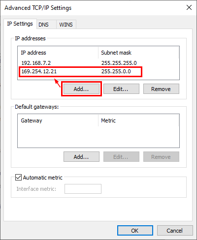
Make sure all BMTS devices and the real-time target machine are turned on and
linked correctly with Ethernet cables. An example setup with three BMTS devices is
illustrated below.
Build and run the generated Simulink model on your target machine.
After a few seconds of runtime, all BMTS devices switch into flash mode and the
Simulink model stops automatically.
Confirm that all of the BMTS devices have switched into flash mode by checking
the SYS LED on each device, which should blink yellow in flash mode.
Only continue with the next step if all BMTS devices have switched into flash
mode. If only some of the devices have switched, power-cycle the entire collection
of BMTS systems and run the Simulink model again.
3. Transfer Firmware Update
The firmware update will be transferred directly from the host computer to the
BMTS devices, without using the real-time target machine.
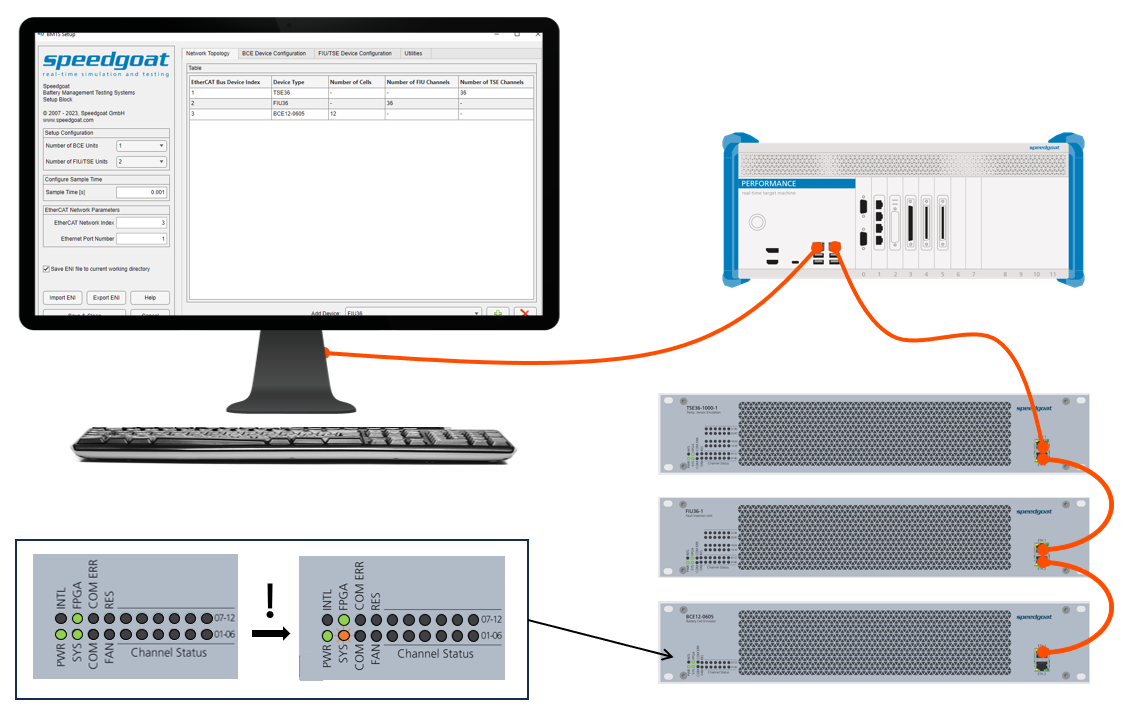
Identify the Ethernet cable which connects the real-time target machine to the
first BMTS device in the daisy chain. Disconnect the cable from the real-time target
machine, and connect it to an Ethernet port of your host computer instead. The
Ethernet port should have DHCP enabled. Alternatively, an IP address from the
link-local address range (169.254.x.x) can be assigned to the host PC Ethernet port.
Otherwise, the BMTS devices may not be able to communicate with the host computer.
An example setup with three BMTS devices is illustrated below.
Wait at least 10 seconds for the DHCP server to assign IP addresses.
Continue with the on-screen instructions to start the firmware update.
The remaining update process is automated. Observe the MATLAB Command Window for
status updates. Verify that all of the devices are detected and updated one after
the other.
The flash process can take up to two minutes per device. Do not interrupt the
update process at this point. However, if any issues occur during the update, these
can usually be fixed by repeating the flash process.
4. Verification
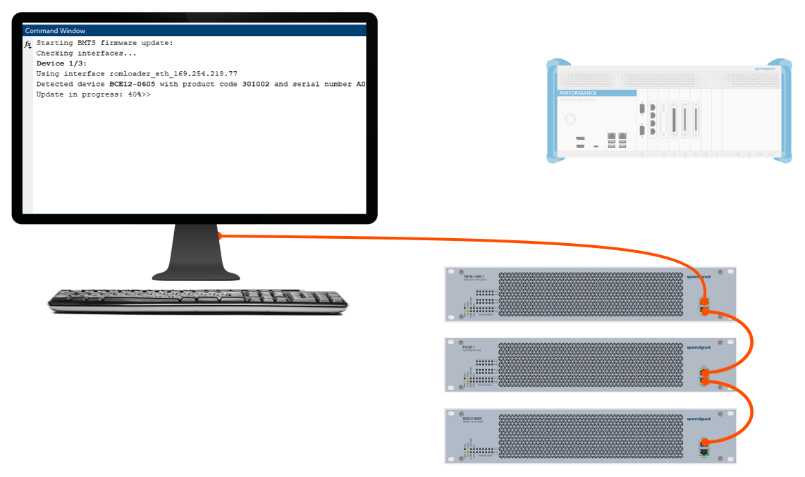
Once the update process is finished, verify that all the connected devices have
updated successfully. It can occur that one or more devices were skipped during the
update due to network discovery issues. This is indicated by the SYS LED still
blinking yellow on affected devices.
If a BMTS device still has a yellow blinking SYS LED, connect that device directly
to your host computer via Ethernet, and disconnect any cable from the second
Ethernet port of the device, to achieve a single point-to-point connection. An
example setup is illustrated below. Then, click "Retry" to update only this device.
Repeat this step for all devices which were skipped before.
After successful transfer of the firmware update to each device, a BMTS device
internal update process is started. This phase can take up to 40 seconds. On newer
firmware versions, this phase is indicated with a yellow RES LED, and completion is
indicated by the RES LED blinking green three times, then the RES LED turns off.
Depending on the previous firmware version, no internal update process may be
required.
When the internal update has finished, the BMTS devices automatically reboot
using the latest firmware. After waiting at least 40 seconds, or when all of the RES
LEDs have turned off, the devices are operational again.
Appendix: Configure Windows Network Settings
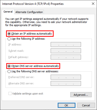
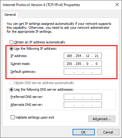
To communicate with the BMTS devices during a firmware update, the used Windows
Network Adapter must either be configured for DHCP, or assigned a link-local IP
address (169.254.xxx.xxx).
In the Windows Network and Sharing Center, configure the Internet Protocol Version
4 Properties for your Ethernet controller as follows (choose one of the
options):
Option 1: Use DHCP
Option 2: Manually assign a link-local IP address (169.254.xxx.xxx)
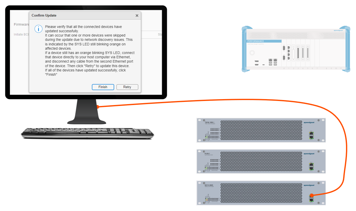
Option 3: Assign an additional link-local IP (169.254.xxx.xxx)
Open the Advanced... settings and add a
link-local IP address: