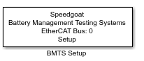
BMTS Setup
BMTS Setup — Configure the BMTS Setup
block
Library
Simulink Real-Time - Speedgoat
Description
![[Note]](images/note.png) | Note |
|---|
This documentation refers to the Speedgoat Battery Management Testing Systems
(BMTS) that are supported with MATLAB R2022a and
later. |
The BMTS Setup block allows the user to configure
an entire EtherCAT chain consisting of the Speedgoat real-time target machine acting
as the EtherCAT main device and a configurable number of Battery Cell Emulator
(BCE), Fault Insertion Unit (FIU) and Temperature Sensor Emulator (TSE)
devices.
The order of the devices listed in the BMTS Setup block must match the order in
which the devices on the EtherCAT bus are daisy-chained. The real-time target
machine is connected to device 1, device 1 is connected to device 2, and so
forth.
The device types and the order of the devices can be changed by modifying the
table in the BMTS Setup block mask.
Ports
This driver block has no input or output ports.
Parameters
Setup Configuration
-
Number of BCE Units
Selects the number of BCE units present in the EtherCAT network. The
value is automatically updated when devices are added or removed. This
parameter can be used to quickly add multiple BCE units at the end of
the table.
-
Number of FIU/TSE Units
Selects the number of FIU/TSE units present in the EtherCAT network.
The value is automatically updated when devices are added or removed.
This parameter can be used to quickly add multiple FIU/TSE units at the
end of the table.
Configure Sample Time
-
Sample Time
Configure the sample time of the data exchange on the EtherCAT
network. All BMTS Read and BMTS Write blocks for devices on this
EtherCAT network will operate with this sample time.
EtherCAT Network Parameters
-
EtherCAT Network Index
The EtherCAT Network Index is a user-defined ID to associate the BMTS
Read and BMTS Write blocks with the corresponding BMTS Setup block. The
value must be an integer between 0 and 11.
-
Ethernet Port Number
Identifies the Ethernet port to be used on the real-time target
machine. The first port reserved for EtherCAT by the
speedgoat.configureEthernet function is port 1. The value only needs to
be changed when using more than one Ethernet port for EtherCAT
communication.
Buttons
-
Import ENI
The Network Topology—namely the table showing all the devices in
order—can be reconstructed from a previously saved ENI (EtherCAT Network
Information) file. Click this button to select an ENI file and load the
topology. When the mask is saved and closed, a new ENI file will still
be generated based on the current table.
-
Export ENI
Generate the ENI file for the current network topology according to
the table and save it to a user-defined location.
-
Help
Opens this help page in the MATLAB Help browser.
-
Save and Close
Saves all settings from the block mask, generates the ENI file, and
configures all the blocks present in the model; this process can take a
few seconds.
-
Cancel
Discard all changes and close the block mask without saving.
Configuration
Network Topology Tab
-
Editing the Table
For existing device table entries, the device type can be changed by
double-clicking the device type and selecting a different device from
the drop-down menu. To change the device order, double-click the
EtherCAT Bus Device Index field of
the respective row and enter a new index; the list will automatically be
re-ordered.
-
Adding and Removing Devices
New devices can be added by selecting the device from the Add Device drop-down menu and then clicking
the + button. To quickly add multiple
devices, you can also increase the Number of
Units drop-down values on the left. After adding devices
this way, the device type can be set directly in the table.
One or multiple table entries can be removed by selecting them in the
table and pressing the red x button. A
confirmation is required before the selected devices are deleted.
BCE Device Configuration Tab
-
Device Selection and Configuration
The device selection drop-down menu lists all the BCE units available
in the table on the Network Topology
tab. Select a device to adjust the settings below for this
device.
Click the Copy and apply to all BCE
devices button to apply the setting to all BCE units on
the network.
| Note |
|---|
The system sends configuration parameters to the BCE when model
execution starts. It may take up to 2 s to apply the data.
Consequently, the system forces all cell enable signals off during
the first 2 s of execution. |
-
Cell Operation Mode
Select either Cell-Auto-Mode or
Cell-Sync-Mode.
In Cell-Auto-Mode, each cell operates
autonomously. Cell output updates are performed sequentially, as soon as
new data has been written to the DAC.
In Cell-Sync-Mode, output updates are
performed simultaneously in all cells. The synchronous cell output
updates are triggered after all DACs have been pre-loaded with new data.
Current monitoring and voltage monitoring are also synchronized
internally for all cells.
-
Current Sink Mode
Select either Manual or Automatic current sink mode.
In Manual sink mode, the cell sink
current is set by the user via the BMTS Write
block.
In Automatic sink mode, the cell sink
current is adjusted automatically based on the difference between the
cell's voltage setpoint and the externally applied voltage.
-
Cell Voltage Averaging/Cell Current Averaging
Select the number of ADC samples to average for each resulting
measurement of cell voltage and cell current.
ADC samples are taken at a rate of 50 kHz. Oversampling reduces
measurement noise by averaging a certain number of samples.
| Note |
|---|
Increasing this value will increase measurement lag. Selecting a
value of 64 or higher causes the update rate to fall below 1
kHz. |
-
Cell Over-Voltage/Under-Voltage/Source Current/Sink Current
Shutdown Limit
Configure upper or lower limit values for each cell's voltage and
current readings. When you enable a shutdown limit by checking the
checkbox and the cell exceeds the limit, it enters shutdown state. In
this state, the system sets the current and voltage to zero, powers down
the DACs, and turns on the red LED. ADCs and the temperature sensor
continue operating to allow uninterrupted cell monitoring.
-
Custom Calibration Values
Click Edit to enter custom gain and
offset values for voltage and current of each BCE cell. Export saves the calibration values for all
BCE devices to a .mat file. It can be imported with Import only if the network topology matches
the layout exactly.
The calibration values are only applied if the Enable checkbox is checked.
For more information, refer to the BCE Usage
Notes.
-
Copy and apply to all BCE Devices
Copies the BCE device configuration parameters from the currently
selected device to all other BCE devices on the network.
Custom calibration values are specific to each BCE and remain
unchanged. Only the status of the Enable flag is copied to other
devices.
BCE AC Signal Modulation Tab
-
Device Selection
The Device Selection drop-down menu
lists all the BCE units available in the table on the Network Topology tab. After selecting a
device, the following AC Signal Modulation settings can be
configured.
-
Enable AC Signal Modulation Mode
To use AC Signal Modulation functionality, this checkbox must be
enabled; otherwise, only the normal operation mode is available.
| Note |
|---|
Ensure that the BCE devices are updated to SoC Firmware version
1.1.0.0 or later before enabling AC Signal Modulation mode. If the
BCE firmware is outdated, the device will not go into operational
mode with AC Signal Modulation mode enabled. |
-
AC Signal Modulation Data
Use the file selector to link a .mat file containing the AC Signal
Modulation data. Data must be provided in the form of an array or a
table with exactly 12 columns and up to 256 rows. Each of the 12 columns
represents AC signal data points for the respective BCE cell to add to
the starting value.
-
Cell-Specific AC Signal Modulation Settings
Select a cell from the list on the left-hand side to configure
additional settings for this cell.
-
Time Step
Set the time step after which the AC Signal Modulation outputs the
next sample from the signal data array. The unit can be set to
milliseconds or microseconds. The minimum value is 7 μs.
-
Output Path
Select whether the AC Signal Modulation data is applied to the cell
voltage or to the cell sink current.
-
Start Time Delay
Add an AC Signal Modulation start time delay for this cell. To achieve
exact synchronization or time offsets between cells, the AC signal must
be started simultaneously for all cells from Simulink. Each cell will
start AC data output after its start time delay has passed.
-
Stop after X Passes Through the Data File
To stop AC Signal Modulation deterministically after a certain number
of iterations, enter the number of passes through the data file after
which to stop AC Signal Modulation. When stopped, the cell returns to
normal operation mode.
-
Gain Adjustment Value
Add an additional gain factor to apply to the data points from the AC
signal data file. The gain value must be in the range of 0 to 2.0.
Setting it to 1 disables the gain adjustment.
-
Gain Sweep Mode
This mode allows the gain value applied to the AC Signal Modulation
data to change periodically. When enabled, the gain adjustment is
updated each time the number of entered time steps have elapsed. The
current gain adjustment value defines the starting point (1 if
disabled); the gain sweep limit value defines the endpoint. Counting
occurs between these two boundaries. If one boundary is reached, the
counting direction reverses. The current gain value is adjusted
(increased or decreased) by the update step value.
-
Timer Sweep Mode
This mode allows the AC Signal Modulation output update time step (or
frequency) to change periodically. When enabled, the time step is
updated each time the number of entered time steps have elapsed. The
current time step value defines the starting point; the timer sweep
limit value defines the endpoint. Counting occurs between these two
boundaries. If one boundary is reached, the counting direction reverses.
The current timer value is adjusted (increased or decreased) by the
update step value.
FIU/TSE Device Configuration Tab
-
Device Selection and Configuration
The device selection drop-down menu lists all the FIU and TSE units
available in the table on the Network
Topology tab. After selecting a device, additional
settings for this device can be configured, namely Synchronous Read mode, Synchronous
Write mode, and TSE Switching
Mode (only applicable to TSE devices). Hover the mouse
cursor over each field for additional tooltip information.
The settings can be applied to all FIU and TSE units present in the
network by pressing the Copy and apply to all
FIU/TSE devices button.
Utilities Tab
-
Read Device Information
By clicking the button Generate
DeviceInfoMdl, a new Simulink model can be automatically
generated. The purpose of this model is to easily read out device
information of all the BMTS devices connected to the target machine.
Note that the network topology must match the configuration set up on
the Network Topology tab. Run the
generated model to read out serial numbers, product codes, and firmware
versions of connected BMTS devices.
-
Firmware Update
By clicking the button Start Firmware
Update, the process to update the firmware of connected
BMTS devices as set up on the Network
Topology tab is initiated. Follow the on-screen
instructions to update the firmware of all connected BMTS
devices.
Firmware updates are provided with new versions of the Speedgoat I/O
Blockset.
For detailed instructions, refer to the BMTS Firmware Update
Instructions page.
-
Export Bus Objects to Data Dictionary
When working with a data dictionary, it can be preferable to have the
BMTS Simulink bus structures saved in the data dictionary instead of the
base workspace. Click the button Export Bus
Objects to DD to export all BMTS bus objects present in
the base workspace and add them to the data dictionary that is linked to
the Simulink model.