ARINC 429 Parser Write
ARINC 429 Parser Write — Sends ARINC 429 words to
one channel
Library
Simulink® Real-Time™ - Speedgoat
Description
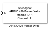
The ARINC 429 Parser Write block consists of a masked subsystem, which adds an
additional functionality layer to the existing IO682 Send block. The subsystem is
dynamically populated with a set of preconfigured ARINC 429 Pack blocks, the
corresponding IO682 Send blocks, preconfigured input ports, and the interconnecting
lines. The ARINC 429 Parser Write block mask allows users to select which
configuration file messages should be transmitted.
The ARINC 429 Parser Write block cannot be edited when linked to a custom library
because the block contains instance-specific data that cannot be shared across
links. The block remains editable within the library itself; changes made there are
reflected in all linked instances. Additionally, the block cannot be used within
subsystem models, as these are not supported.
Each Write block has a software FIFO buffer in which Tx messages are queued. When
selecting the sample time of the Write block, the user must ensure that all messages
can be transmitted within a single sample step and that the bus is not
overloaded.
Ports
Inputs
-
Enable Input
This input port is available whenever the Show
Enable Input checkbox in the block mask is activated. Use
this port to enable (1) or disable (0) the transmission of ARINC 429
messages during runtime. Each message may be controlled using an
n-elements boolean vector, where n represents the number of messages
from the configuration file that are enabled in the ARINC 429 Parser.
The indexing of the messages aligns with the enabled nodes in the tree,
in ascending order.
-
Tx
The input port expects a Simulink bus containing the signals that
should be transmitted. The Mapping Tab
allows you to map these signals to the ones defined in the selected
database.
Parameters
I/O Module Configuration
-
Module ID
Selects the IO682 I/O module with which this driver block
communicates. The list is populated according to the IO682 Setup blocks
in the model.
-
Channel
Select the IO682 channel with which this driver block communicates.
Database
-
Browse
Select a configuration file from your folders by clicking the browse
button.
Refer to the Usage Notes for more
information about the configuration file.
-
Update
Use this button if the configuration file changes.
Transmission Control
-
Use Cycle Times from Database
Select this option to transmit ARINC 429 messages with the cycle time
defined in the selected configuration file. If disabled, ARINC 429
messages are transmitted at the selected block sample time by
default.
-
Show Enable Input
Select this option for Enable Input
Port to be available. With this port, messages can be
enabled or disabled during execution.
Sample Time
-
Sample Time
Defines the base sample time at which this driver block gets its sample hit. This
parameter can also be set to -1 for inherited
sample time. The units are in seconds.
Hierarchy Tab
All messages defined in the selected configuration file are displayed in the
Hierarchy tab. Detailed information about the
various signals is displayed when a specific message is selected.
The CycleTime message property is supported
provided that all cycle times are a multiple of the Sample
Time parameter. To use this feature, check the Use Cycle Times from Database checkbox. If no cycle time has been
defined for a message, it defaults to the configured Sample
Time.
Hierarchy Tree
-
Search
The Hierarchy tree has a Search field available, which highlights
nodes found in this tree. You can cycle through highlighted nodes using
the up and down arrow buttons next to the Search button. Clear the Search field to clear the node highlighting.
-
Refresh
This button refreshes the Hierarchy
tree and the Details Table.
-
Expand
This button expands or collapses all nodes in the Hierarchy tree.
-
Enable all
Allows users to enable or disable all available messages in one
click.
-
Group by
Allows users to sort the messages either by None, Equipment, or
Channel.
Details Table
The Details Table shows all the
information available in the configuration file for the selected node.
Depending on the hierarchy level, different types of information are
displayed. No actions are available for this table.
Mapping Tab
The mapping functionality allows you to map the elements of an input bus signal to
the signals defined in the selected database file. On the Hierarchy tab, first select which messages are transmitted, and then
switch to the Mapping tab. At this point, it is
important to ensure that there is an input Simulink bus signal on the input port of
the block.
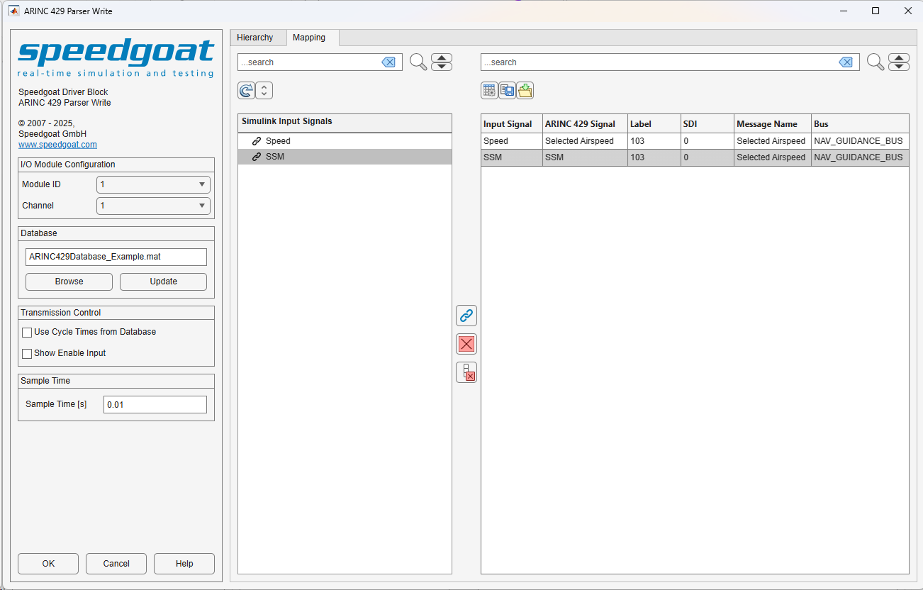
The Mapping tab shows a tree view of the
structure of the input Simulink bus signal on the left, and the mapping table on the
right. The mapping table contains the list of signals that were previously selected
in the Hierarchy tab, and an Input Signal column that shows how an element of the input Simulink
bus signal maps to a corresponding database-defined signal. When no mapping is
selected, the input signal in the mapping table takes the default value Ground (0). To map signals, you must select the desired
input signal elements in the left-hand tree view, the corresponding row in the
right-hand table, and click the arrow button to complete the mapping.
The following options are available in the Mapping tab:
Refresh button: If the input Simulink
bus signal is modified, click this button to refresh the tree
view
Clear Selected: The signal currently
selected in the mapping table is set to the default value Ground (0)
Clear All: All signals in the mapping
table are set to the default value Ground
(0)
Map Button (arrow icon): Maps an
input signal element to a database-defined signal. To enable the button,
both a signal from the tree view and a row from the table on the right
must be selected. Once a signal is mapped, the signal's icon in the tree
view changes to a link
Configure Table: Opens a dialog
window where you can use checkboxes to configure the columns visible in
the mapping table
Save to File: Saves the mapping table
to a file, where the file name and the file type are selectable in a
dialog box. The file types currently supported are .csv and .mat
Load from File: Invokes a file
selection dialog to load the mapping table from a file. The file types
currently supported are .csv and
.mat. The table layout of the
loaded file must match the layout of the file created when you click the
Save to File button. To ensure that
the mapping table is valid, all the mapped messages must be enabled and
all the input signals must be available in the connected input Simulink
bus signal. Disabled messages are not loaded into the mapping table
(indicated by a warning message). The input signals unavailable are
displayed as invalid in the mapping table.