IO623 Usage Notes
IO623 Usage Notes —
Usage information about the I/O module
Interrupt Setup
Introduction
The communication in a FlexRay cluster is facilitated by the TDMA method (Time
Division Multiple Access). Each node has pre-defined time slots to send data
packets. Each communication controller (CC) has an internal clock, which is
synchronized over the FlexRay network. The clocks must be synchronized to avoid the
frames of two nodes colliding.
The clock on which the Simulink model runs, however, is part of the target machine
and is therefore not synchronized with the clock of the FlexRay CCs. To ensure a
deterministic behavior, we must trigger the IO623 driver blocks using the IO623 CC1 interrupt, which is generated at the start of
each communication cycle (see graphic below).
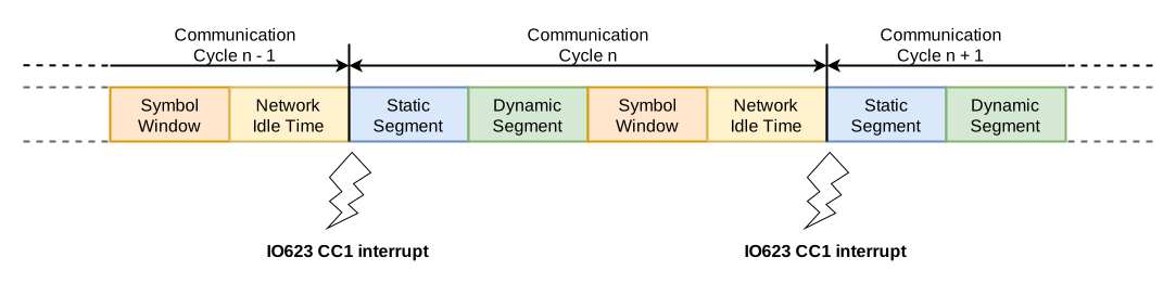
Currently, the interrupt is only generated by CC1. This means you will always need
to configure CC1 and connect it to the FlexRay bus, even if your I/O module contains
multiple CCs.
The Interrupt Setup block represents hardware interrupts from Speedgoat I/O
modules. It is used to trigger an asynchronous subsystem or provide the pulse for a
model base rate. Refer to the Interrupt Setup help
page.
Run the following command in the MATLAB command window:
speedgoatlib_interrupt
Drag and drop the Interrupt block to your model. Alternatively, you can find the
Interrupt Setup block by entering speedgoatlib in the MATLAB command window, and
then navigating to Tools & Utilities >
Utilities. Double click the Interrupt Setup
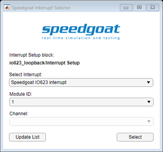
block, and then select Speedgoat IO623 Interrupt in
the Select Interrupt list (the IO623 Setup block
must be in your model). Select the corresponding Module ID, and then click Select, Apply, and
OK.
Pulse for model base rate
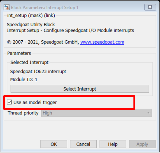
When using the model in the base rate, select the Use as model trigger option in the block mask.
Triggering an asynchronous subsystem
When using an asynchronous subsystem, unselect the Use as model trigger option.
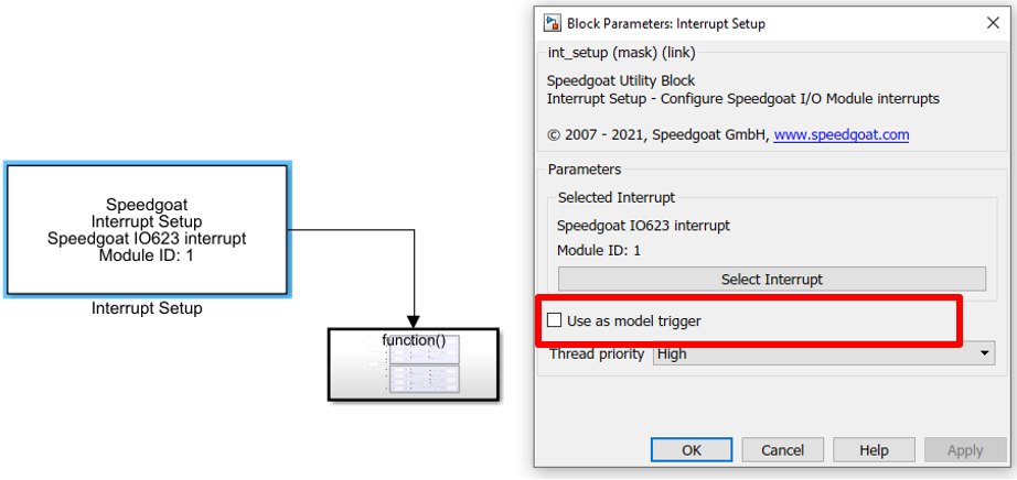
Move all the IO623 blocks inside a subsystem. Connect the output of the
Interrupt Setup block to the trigger input on top of the subsystem.
LED Indicators on the Front Panel
Each FlexRay channel (A and B) on the front panel has two LED indicators for
signaling different monitoring states: Red and green. If no LED is lit, then no CC
is installed at the corresponding connector or no bus activity is detected. The LED
states are explained in the following table:
Configuration of FlexRay Controller using FIBEX File
A configuration file, namely a CHI file, is required for every CC on your IO623
I/O module. CHI files define all the necessary FlexRay parameters for the CC to
connect to (or start up) a FlexRay cluster and send and receive frames.
With our CHI Generator Tool you can load a FIBEX file, which contains the
configuration for a whole FlexRay network, and export the CHI files for the
different CCs. You can download the CHI Generator from the Speedgoat Customer
Portal.
Also, part of the CHI file is the receive and transmit buffer configuration. A
message buffer RAM with 2048 32-bit words is available for the creation of these
buffers. Each message buffer uses 16-byte administrative data. The remaining space
can be used for the payload. This leads for example to a maximum configuration of 30
message buffers with a 254-byte payload, 56 message buffers with a 128-byte payload
or 128 message buffers with a 48-byte payload. The maximum number of message buffers
is 128.
Every frame that needs to be sent by the CC requires a transmit buffer to hold the
data until it is ready to be sent. The data written to the IO623 Send blocks will be
written directly into these buffers for optimal performance. For the receive
functionality, the buffer configuration is less critical. You can specify dedicated
buffers to receive specific frames. Unused message buffers will be configured as
general-purpose receive buffers which can receive frames from any slot (the driver
requires at least a few of these general-purpose buffers to be present). The frames
received will then be buffered in a 2 MB SRAM. This allows you to receive all
frames during a FlexRay cycle.
Speedgoat CHI Generator - User Manual
Introduction
The Speedgoat CHI Generator is exclusively used to create RBS CHI files for the
IO623 Setup block.
The Speedgoat CHI Generator configures the CC based on the FIBEX database. It is
an intuitive tool to generate RBS CHI files based on FIBEX files. The special
characteristic is that the files help to stimulate one or more Electrical Control
Units (ECUs) from the FIBEX file. That means that the CC is configured to send all
messages received by the ECU (Device Under Test DUT). Message dependencies to other
DUTs are resolved and considered. Furthermore, the user has the option to switch off
individual frames and add additional frames. Consequently, an adaptation of the RBS
CHI files for changed development levels is clean.
Main Features:
Select one or more FIBEX DUT
Select the DUT whose messages should be sent at any rate
Switch off and on individual frames
Add additional frames
Generate several RBS Controllers for load sharing and
synchronization
Add Sync messages if it is necessary
Support FIBEX versions: 1.2.0a, 2.0.0d, 2.0.1, 3.0.0, 3.1.0, 4.0.0, 4.1.0,
4.1.2
Control FIBEX data including schema validation and additional rules
Support CC for the CHI file
Bosch E-Ray
FreeScale MFR4200, MFR4300, MFR4310, MPC5567
Fujitsu MB88121, MB91F465X
NEC V850E/PH03
Automatic message buffer mapping
System Requirements:
Microsoft Windows 10 (32-bit or 64-bit)
Minimum disk space 30 MB
Internet Explorer 6.0 or higher
Windows Installer 4.5 or higher
Microsoft .NET Framework 4.7.2 (To run the application the Microsoft .NET
Framework is necessary. Please visit the Microsoft homepage for requisites
and download)
Installation
To install the Speedgoat CHI Generator, the Speedgoat_CHI_Generator_32Bit.msi or
Speedgoat_CHI_Generator_64Bit.msi packages are required. Use the correct
installation package for the operating system (the 32-bit package will not work on a
64-bit operating system and vice versa). Start the installation by double-clicking
the installation package and follow the installation wizard instructions.
Start Speedgoat CHI Generator
Start the application by clicking the [Start] button from the Windows taskbar and
then selecting StarCooperation -> Speedgoat CHI Generator -> Speedgoat CHI
Generator.
To run the Speedgoat CHI Generator, a license per PC and person is needed. Then on
the first start of the Speedgoat CHI Generator, the following window is
shown.
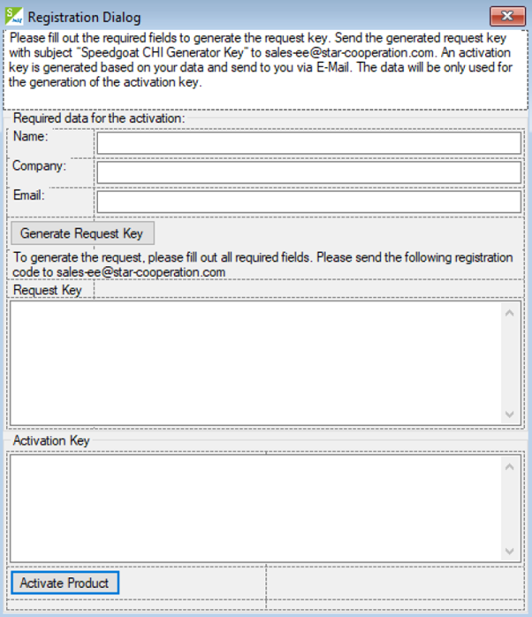
Please fill out your name, company, and email address. Then click “Generate
Request Key”. Copy the generated code into an email and send it to
sales-ee@star-cooperation.com. (You can close the dialog box by clicking on the
X-button.)
After the personal registration key is generated, it will be sent to you by email.
When you start the application, the registration window is shown again. Copy the
registration key into the Activation key text field and then click on the “Activate
Product” button. The Speedgoat CHI Generator main window will now display.
Speedgoat CHI Generator GUI overview
The most important options are described.
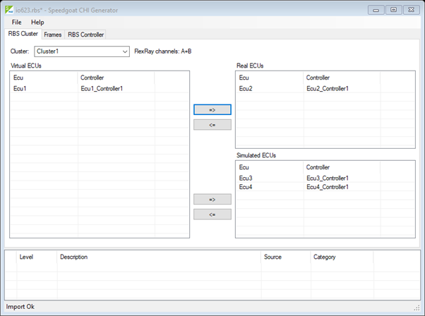
File menu:
Speedgoat CHI Generator can start from Command Prompt and open an RBS or FIBEX
file.
Navigate to the installation path (e.g. cd “C:\Program
Files\StarCooperation\Speedgoat CHI Generator”), to open the file with path
c:\files\myProject.rbs type in the Command Prompt: ChiGenerator4Rbs.exe
c:\files\myProject.rbs
A relative file path is also supported: ChiGenerator4Rbs.exe
..\..\..\myProject.rbs
When the path contains spaces (e.g. c:\My Documents\fibex.xml), enclose the file
path with quotation marks: ChiGenerator4Rbs.exe “c:\My Documents\fibex.xml”
RBS Cluster tab:
Cluster drop-down box: Select one of the
FIBEX file clusters. The FlexRay channels used (A, B or, A + B) of the
selected cluster are shown on the right of the drop-down box
Virtual ECUs window list: Contains all
ECUs of the selected cluster. After the import of a FIBEX file, all ECUs are
virtual. This means the ECUs are not physically available on the bus. Only
the frames which depend on a real (physical available) ECU are sent on the
bus
Real ECUs window list: Contains all ECUs
which are physically available on the bus -> DUT
=>, <= move buttons: The selected ECUs
can be moved from the Virtual ECUs list to
the Real ECUs list and back. Similarly, the
mouse can be used to drag and drop the ECUs between the lists
Simulated ECUs window list: Contains all
ECUs which are not physically available but from which all Tx frames should
be transmitted by the RBS
=>, <= move buttons: The selected ECUs
can be moved from the Virtual ECUs list to
the Simulated ECUs list and back.
Similarly, the mouse can be used to drag and drop the ECUs between the
lists
Frames tab:
The Frames tab shows the resulting RBS frames
from the RBS Cluster configuration. The frame configuration gives the possibility to
add or disable frames. If there are not enough sync or startup frames, an existing
frame can be configured as a sync or startup frame, or new sync/startup frames can
be added.
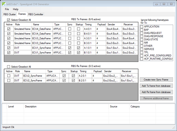
Ignore following frame types for Tx
checkboxes: Frame type filter for special frames. By marking one or
several checkboxes, the selected frame type can be excluded from the
RBS
Create new Sync Frame button: New
sync or startup frame can be created and added to the RBS Tx frames in
the Create new frame window
Create new frame window:
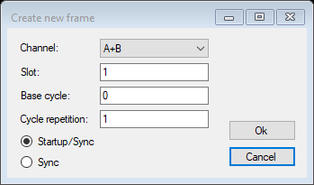
Channel drop-box:
Select the channel on which the new frame should be
sent. Only channels that are available for the cluster
can be selected
Slot text box: The
slot to send the frame in
Base cycle text box:
The base cycle to send the frame
Cycle repetition text
box: The cycle repetition with which to send the
frame
Startup/Sync and
Sync option
buttons: Configure the frame as startup/sync or sync
frame
Ok and Cancel buttons: Confirm or
cancel the dialog. If the dialog is closed by using the
Ok button, the
configured frame is added as User
generated startup/sync frame to the RBS
Tx frames
RBS Controller tab:
The RBS Controller tab shows the controller in
the configured frames when the RBS to send and receive is used
Every time the tab is clicked, the Select
hardware window pops up to select and configure the RBS hardware. If
the RBS hardware was already selected, the Select
hardware window contains the configuration settings indicated
immediately below.
Select hardware window:
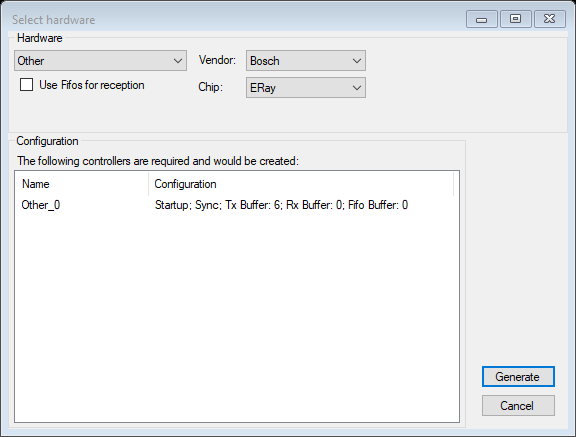
Drop-down box: The hardware option StarElectronics
hardware (with CC vendor and chip presets) is used
for the RBS. The hardware option Other allow users to specify their own hardware
(vendor/chip combinations; but only supported CCs can be
selected)
Use Fifos for reception checkbox:
Configure the CCs to use first-in, first-out (FIFO) buffers for the
reception. If the checkbox is selected, 4 FIFO buffers will be
created
Vendor drop-down box (only
enabled if Other in the Hardware drop-down box is selected):
Select the CC vendor. Only supported vendors are available for
selection
Chip drop-down box (only enabled
if Other in the Hardware drop-down box is selected):
Select the CC chip. Only chips for the supported selected vendor are
displayed
Configuration The following controllers are
required and would be created window list: Show how many RBS controllers will be
created and which configuration they will have. The following
configurations are shown: Startup and sync flag when configured. The
number of Tx buffers. The number of Rx buffers. The number of FIFO
buffers
Generate button: Confirm or
cancel the Select hardware window.
If the window is closed by using this button, the configured
settings are created and used for the RBS to generate the RBS CHI
files