Documentation search search close
CONTENTS
https://www.speedgoat.com/help/slrt/page/icon_documentation.jpg
v10.0.1.x for R2026a
View other versions

IO623 Pin Mapping

IO623 Pin Mapping — Reference information about the I/O module connector

I/O Module Front Connector
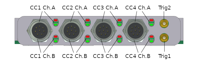
One bus connector contains both FlexRay channels A and B. The LED indicator states are described in the usage notes.

The trigger lines Trig1 and Trig2 do not provide any functionality yet.

Front view of the 8-pin Binder 712 female connector

PinSignal
1Shield
2GND
3Ch. A: Bus +
4Ch. A: Bus −
5Ch. B: Bus +
6Ch. B: Bus −
7-
8GND

Cable

Front view of the 9-pin D-sub female connector (on the cable)

PinSignal (combined cable)Signal Bus A (split cable)Signal Bus B (split cable)
1---
2Ch. A: Bus −Ch. A: Bus −Ch. B: Bus −
3Ch. A: GNDGNDGND
4Ch. B: Bus −--
5ShieldShieldShield
6Ch. B: GND--
7Ch. A: Bus +Ch. A: Bus +Ch. B: Bus +
8Ch. B: Bus +--
9---