IO611 Usage Notes
IO611 Usage Notes — Usage information about the
I/O module
CAN Read Strategy
The "CAN Read" block reads one message from one channel of the module input queue.
The "Data present" output port shows if there are more messages available in the
queue.
The CAN receiver requires a do-while construction to ensure that all messages in
the buffer are read at a given sample step. It is important to estimate the number
of messages expected so that the correct sample time of the do-while subsystem is
selected. The sample time of the subsystem is defined by Simulink inheritance rules:
if the subsystem does not have input ports, it will inherit the fundamental sample
time of the model. Alternatively, the sample time of the subsystem can be controlled
by adding an input port. The sample time of the block connected to the input port is
inherited by the subsystem.
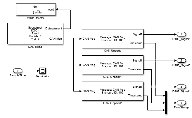
The do-while construction iterates the CAN Read operation until the receiver
buffer is empty (this information is provided by the Data present port). In the same
subsystem, we can filter the messages required by the application.
The sample time must be chosen in order to avoid buffer overflow during a sample
step. Furthermore, if multiple messages with the same Message ID are received, only
the most recent messages will appear in the do-while subsystem output. To read all
messages with a certain ID, the do-while subsystem must be run faster than the
frequency of the message(s) in question.
For example, if Message ID 100 is expected with a frequency of 10 ms, and all
these messages must be read, the do-while subsystem sample time must be faster than
10 ms, for example, 5 ms.
If there are other messages in the line, a check must be carried out to ensure
that there is no message overflow; for example, with a buffer size of 501 messages
(IO612), if 500 messages are expected within 500 ms, a sample time of 500 ms or
slower may lead to the messages in the buffer being overwritten.
Top Level View:
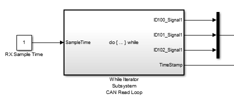
Inside the While Iterator Subsystem
The "Sample Time" input port defines the rate at which the subsystem is executed.
Otherwise it will run on the base rate.
CAN Message Filtering
The module has some limited message identifier filtering capabilities. The filters
are handled on the module level, so rejected messages do not add to the model
execution latency.
Here are two examples of how to configure CAN message ID filtering. Both of these
work with the Acceptance parameter for extended CAN IDs ('Acceptance = [ExtMask,
ExtCode];'). The Acceptance parameter for standard IDs works in the same way.
These parameters are configured in the Setup driver block.
To filter specific ID:
ExtMask = double(hex2dec('1FFFFFFF')) - masks all 29 bits of the ID
ExtCode = double(hex2dec('7DO')) - first ID to filter is 0x7D0
In this case, the message ID 0x7D0 is accepted.
To filter a group of IDs smaller than a certain value:
ExtMask = double(hex2dec('1FFFFF00'))
ExtCode = double(hex2dec('00000000'))
In this case, only IDs below 0x100 (256) are accepted.
![[Note]](images/note.png) | Note |
|---|
The Acceptance parameter takes decimal values. As it is often easier to work
with hex for CAN IDs, we use MATLAB conversion functions here for simplicity.
|
Initialization and Termination CAN Messages
The CAN Setup driver blocks for the supported CAN boards allow you to define CAN
messages to be sent during initialization and termination of the real-time
application. The driver blocks send these messages once at the beginning of each
application run and once before an application run is stopped. The main purpose for
sending these messages is to initialize or terminate other CAN nodes on the network,
such as CANopen or DeviceNet nodes. Even if the CAN layers are not directly
supported, the model can usually communicate with these nodes with standard CAN
messages, provided the nodes are initialized. The initialization and termination
fields of the Setup blocks are intended for this purpose.
You define the initialization and termination CAN messages by using MATLAB® struct
arrays with CAN-specific field names. This approach was also used for the RS-232 and
general counter driver blocks found in the Simulink® Real-Time™ I/O library. Refer
to these driver blocks and their help for additional information about this basic
concept.
The CAN Setup block-specific field names are the following:
Port: Selects the CAN channel over which the message is sent. Valid values
are either 1 or 2 (double). The term Port is used here instead of the
correct term Channel in order to maintain backwards compatibility.
Protocol: Select the CAN protocol. Valid values are either "CAN" or
"CAN-FD" (character vectors).
BRS: Defines if fast data baud rate should be used for CAN-FD. Valid values
are either 0 for standard baud rate or 1 for fast data baud rate
(double).
Type: Defines whether the message to be sent is a standard or extended
type. Valid values are either "Standard" or "Extended" (character
vectors).
Identifier: Defines the identifier of the message. The value (scalar)
itself must be in the corresponding identifier range (standard or
extended).
Data: Defines the data frame to be sent out along with the CAN message.
The length of the row vector defines the data frame size. The limits depend
on the settings for "Protocol".
Pause: Defines the amount of time, in seconds, that the Setup block waits
after this message has been sent before sending the next message. Valid
values are 0–0.05 seconds. Some CAN nodes need time to settle before they
can accept the next message. For example, the node must settle when the
previous message puts it in a new operational mode. Use this field to
specify the idle times (double).