IO601 Pin Mapping
IO601 Pin Mapping — Reference information about
the I/O module connector
I/O Pin Mapping for CAN and LIN:
For proper operation, a CAN topology requires electrical termination in the form
of resistors.
The IO601 I/O module does not include termination resistors. The full resistor
comes with the CAN module loopback cable provided by Speedgoat.
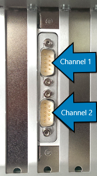
Channel Location
When the module is mounted vertically in the real-time target machine
(Performance, Audio, Modular), channel 1 is on the top connector, and channel 2 is
on the bottom connector. See the image below:
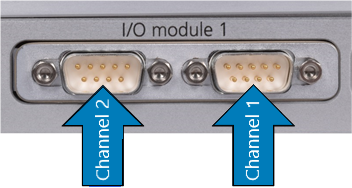
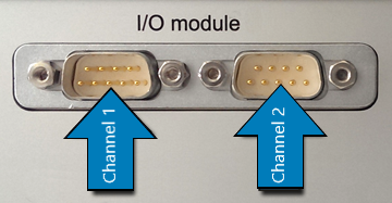
When the module is mounted horizontally in the real-time target machine (Mobile,
Openframe, Education, Automation), the channel number depends on the orientation of
the I/O module. See image below:
![[Caution]](images/caution.png) | Caution |
|---|
Please check the DSUB connector orientation, to identify the channel number.
|