I2C Usage Notes
I2C Usage Notes — Usage
information about the I/O module
Code Module Description
Speedgoat provides two I2C master and two I2C slave code modules for the
configurable I/O modules. This chapter explains, how to use them
Master Read v1 - The I2C
Master read driver block allows data to be read from a slave device
supporting the I2C slave protocol.
Master Write v1 - The
I2C Master write driver block allows data to be written to a device
supporting the I2C slave protocol.
Slave setup v1 - The I2C
Slave setup block allows an identifier (slaveID) to be assigned to the I2CS
blocks
Slave read v1 - The I2C Slave read driver block allows the
register bank of the code module to be read
Slave write v1 - The I2C
Slave write driver block allows data to be written to any register in the
register bank of the code module
I2C Master Read without Subindex, Read Value from Current Model Step
The image below illustrates the basic timing interaction between the CPU, the FPGA
and the I2C slave device without subindex and present model step data (Enable Subindex Configuration is OFF / Read Value from Previous Model Step is OFF).
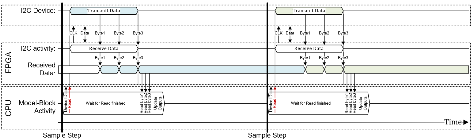
The driver sets the Device ID and then starts the I2C read transfer. The driver
actively waits until this I2C read transfer is finished and updates the model-block
Data output with the I2C data that just have
been transferred.
I2C Master Read with Subindex, Read Value from Current Model Step
The image below illustrates the basic timing interaction between the CPU, the FPGA
and the I2C slave device with subindex and present model step data (Enable Subindex Configuration is ON / Read Value from Previous Model Step is OFF).
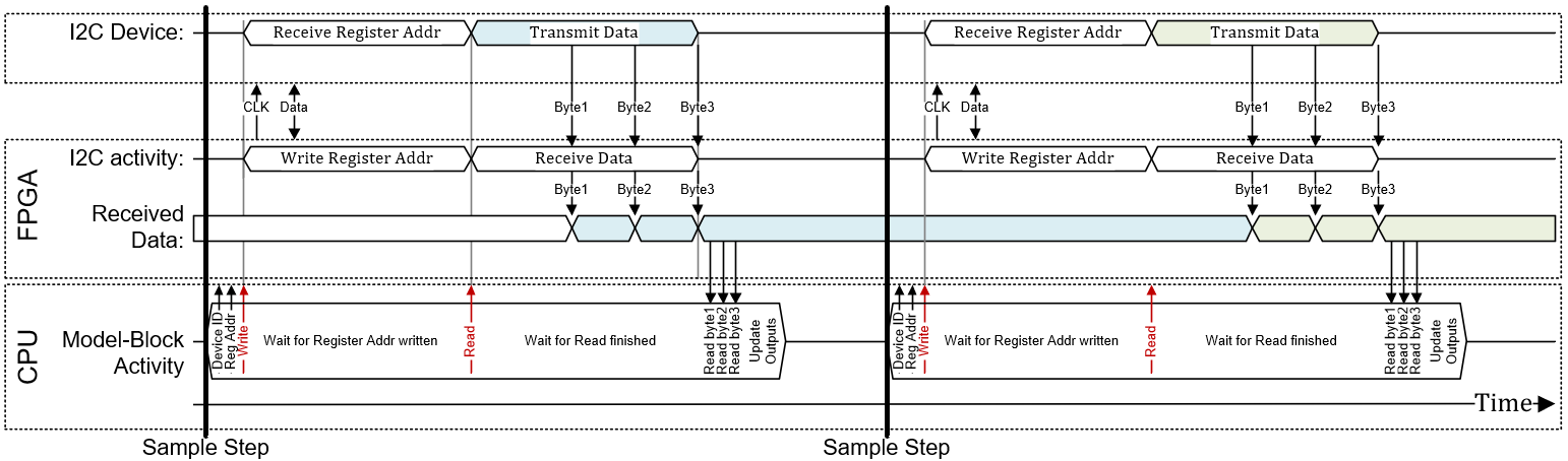
The driver sets the Device ID and the subindex (Reg Addr) and then first starts a
I2C write transfer. This transfer writes the register address to read from to the
I2C device. At the end of this write transfer (active wait), the driver immediately
starts an I2C read transfer where data from the I2C - with the first read address
just written before - are received by the code module. The driver actively waits
until this I2C read transfer is finished and updates the model-block Data output with I2C data that just have been
transferred.
I2C Master Read without Subindex, Read Value from Previous Model Step
The image below illustrates the basic timing interaction between the CPU, the FPGA
and the I2C slave device without subindex and previous model step data (Enable Subindex Configuration is OFF / Read Value from Previous Model Step is ON).
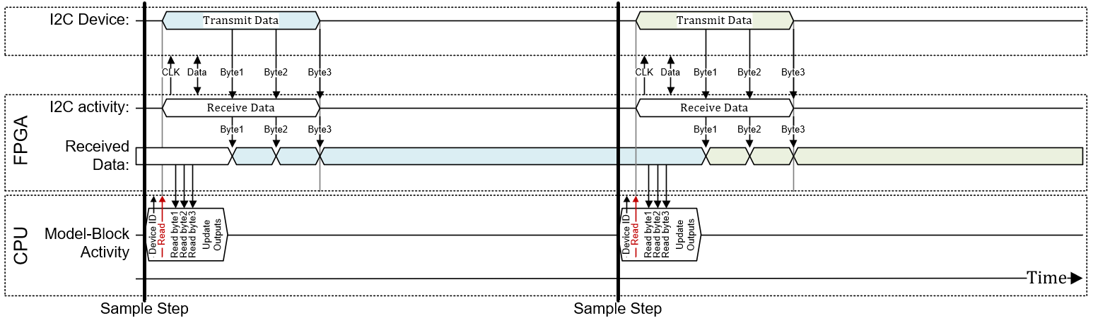
The driver sets the Device ID and then starts the I2C read transfer. The driver
does not actively wait for this I2C read transfer and therefore updates the
model-block Data output with the I2C data from the
previous step. This reduces the TET.
I2C Master Read with Subindex, Read Value from Previous Model Step
The image below illustrates the basic timing interaction between the CPU, the FPGA
and the I2C slave device with subindex and previous model step data (Enable Subindex Configuration is ON / Read Value from Previous Model Step is ON).
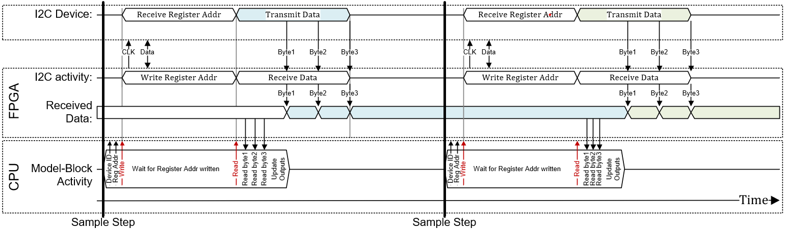
The driver sets the Device ID and the subindex (Reg Addr) and then first starts a
I2C write transfer. This transfer writes the register address to read from to the
I2C device. At the end of this write transfer (active wait), the driver immediately
starts an I2C read transfer where data from the I2C - with the first read address
just written before - are received by the code module. The driver does not actively
wait for this I2C read transfer and therefore updates the model-block Data output with the I2C data from the previous step.
This reduces the TET.