I2C - Slave read v1
I2C - Slave read v1 — The I2C Slave read driver
block allows the register bank of the code module to be read. This read
operation is asynchronous with the I2C protocol.
Library
Simulink Real-Time - Speedgoat
Description
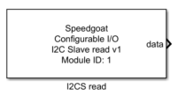
The I2C Slave read driver block allows the register bank of the code module to be
read. This read operation is asynchronous with the I2C protocol.
Ports
This driver block has one data output port and three additional outputs which can
be enabled with the show settings.
Outputs
-
Data
The data read from the register map. The output port width is equal to
the number of registers as configured with the Registers parameter.
-
Data valid
The data valid indicates if the value on the data output port is new
or was already read in a previous sample step. A new value from the I2C
slave buffer is indicated with a 1 and an old value with a 0. The output
port width is equal to the number of registers as configured with the
Registers parameter.
-
Last register
The last register output port shows the last register that has been
written by the I2C Master.
-
Last register valid
The last register valid indicates if the value on the Last Register
output port is new or was already read in a previous sample step. A new
value from the I2C slave buffer is indicated with a 1 and an old value
with a 0.
Parameters
Tab: Module Setup
-
Configurable I/O Module ID
This parameter associates a code module block with a configurable I/O module setup
block. Set this value to match the Module ID defined in the setup block of the
required configurable I/O module.
-
Channel
The number of the channel which this driver block entity will access. Only one
channel per driver block can be addressed. You can specify channels in the range 1-N
(N = the number of channels implemented in your specific configuration file defined
in the Setup block).
-
Registers
A vector which defines the registers to read. Registers are numbered
in the range 1 to 256.
-
Sample Time
Defines the base sample time at which this driver block gets its sample hit. This
parameter can also be set to -1 for inherited
sample time. The units are in seconds.
Tab: Input and Output Port Configuration
-
Show data valid port
When this parameter is set, the data
valid output is shown.
-
Show last register port
When this parameter is set, the last register
Output is shown.
-
Show last register vaild port
When this parameter is set, the last register
valid output is shown.