Serial - Setup v1
Serial - Setup v1 — The Serial setup allows to
configure the Serial Communication for each channel.
Library
Simulink Real-Time - Speedgoat
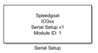
Description
The Serial code module sends and receives UART words.
Ports
This block has no input ports and no output ports.
Parameters
Tab: Module setup
-
Configurable I/O Module ID
This parameter associates a code module block with a configurable I/O module setup
block. Set this value to match the Module ID defined in the setup block of the
required configurable I/O module.
-
Channel Vector
A vector of channels this driver block entity will access. You can specify
channels in the range 1-N (N = the number of channels implemented in your specific
configuration file defined in the Setup block). The width of this vector also
defines the subsequent size of some of the following parameters if scalar expansion
applies. With a single block, all the channels of the block are synchronized.
Tab: Bitrate setup (Simple)
-
Bitrate configuration
This pop-up allows to switch between Simple configuration and Advanced
configuration. The options below are available when the pop-up is set
with "Simple" option.
-
Bitrate vector
Bitrate values expressed in bits per second.
-
Effective bitrate
This disabled text field shows the effective bitrate as computed based
on the I/O module performance.
-
Error (%)
This disabled text fields shows the variation between the bitrate and
the effective bitrate. The units are in percentiles. For instance: 0.16
means 0.16%.
Tab: Bitrate setup (Advanced)
-
Bitrate configuration
This pop-up allows to switch between Simple configuration and Advanced
configuration. The options below are available when the pop-up is set
with "Advanced" option.
-
Effective bitrate
This disabled text field shows the effective bitrate as computed
according to this equation:
-
Base clock frequency vector
This parameters defines the "BaseFrequency" of the above equation. Its
value depends on your configuration file implementation.
-
Clock Divider vector
A 16-bit value for DLL and DLM registers.This parameter defines the
"Divider" element of the above equation.
-
Clock Prescaler vector
This parameter defines the "CPR" element of the above equation.
Correct values are in the range 1 to 31.
-
Time Clock Register vector
This parameter defines the "TCR" element of the above equation.
Correct values are in the range 4 to 16.
Tab: UART frame
-
Parity
From the list, choose - None - Even - Odd - Mark - Space. This
parameter defines the receive and transfer parity.
-
Number of data bits
This parameter defines the data length of the UART word. Correct
values are in the range 5 to 9.
-
Number of stop bits
This parameters defines how many stop bits are used by the protocol.
Correct values are in the range 1 to 2.
Tab: RS485
-
Enable RS485 half-duplex
When checked, the Serial TX line is disconnected from the bus (high
impedance) as soon as data is no longer sent.