Quadrature Usage Notes
Quadrature Usage Notes — Information about the I/O module
Quadrature Encoding
A quadrature encoder uses a wheel with slots (teeth) to indicate the position of
the shaft (high and low side, or black and white in the figure below). This wheel is
emulated by the QAE (Quadrature Encoding) code module. The following image shows an
example with a wheel that contains 8 slots:
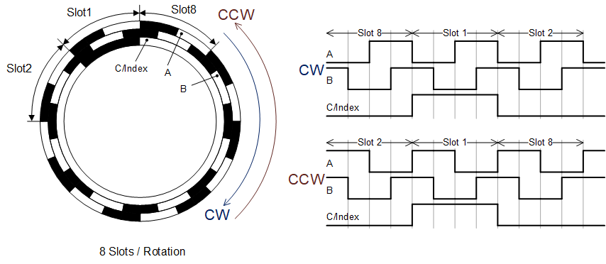
When rotating CW (clockwise), the A signal is leading, when rotating CCW
(counterclockwise), the B signal is leading.
Quadrature Encoding Signal Parameterizing
The following image shows the parameterizing of the quadrature signals:
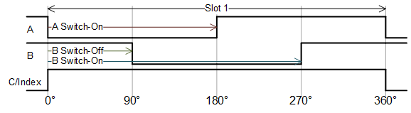
Note that the parameterizing of the quadrature signals is valid for all slots
(the image shows only slot1) and the parameterizing is CW (clockwise) rotation
oriented.
Quadrature Encoding Position Outputs
The following image shows the details of the outputs of the QAE driver
block:
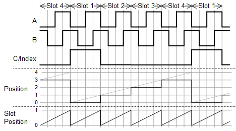
Note that the Position [Number of Slot]
output starts from 0 and counts to the number of slots minus 1. The Slot Position output is a fraction between 0 and 1.
This information can be used for a precision positioning function (to be added
manually).
Quadrature Encoding Interrupt Signals
The following image shows the details of the signal interrupting:

The Single and Dismiss
High parameters are shown in the gray boxes.
Quadrature Decoding
A quadrature decoder requires three lines: A, B, and C/Index. Lines A and B
provide information on position and direction, and C/Index provides information on
the incremental encoder sensor signal measuring pulses for completed revolutions.
The QAD (Quadrature Decoding) code module can be parameterized for different
operating modes.
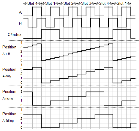
The following image shows the behavior of the Position
[Number of Slot] output for the different modes which are set with
the Captured Signal Edges parameter:
Quadrature Decoding Extrapolation
The following image shows the extrapolation functionality:
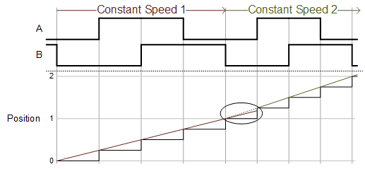
Note the extrapolation is only 100% correct if the speed is constant. If the
speed increases, the extrapolated position value is too low (as shown in the
above image). If the speed decreases, the extrapolated position value will be
too high.
Quadrature Decoding Speed Filter
The A- and B- signals are not always perfectly shifted by 90°. Since the speed
calculation uses the delta times between two detected signal edges, this can
lead to non-stable speed values, even if the speed of the rotating wheel is
constant. This issue is depicted in the following figure:
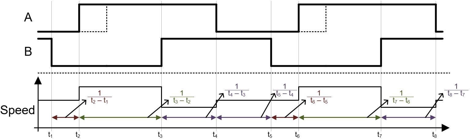
The same issue can be observed if the ratio [capturing frequency / quadrature
signals frequency] is below a certain value.
For this issue, the speed filter can improve the speed measurement. The filter
calculates the average of the last elapsed delta times. The amount of elapsed
delta times can be set with the Speed Filter
Width parameter. The following image explains the setting with
Speed Filter Width parameter set to
4:
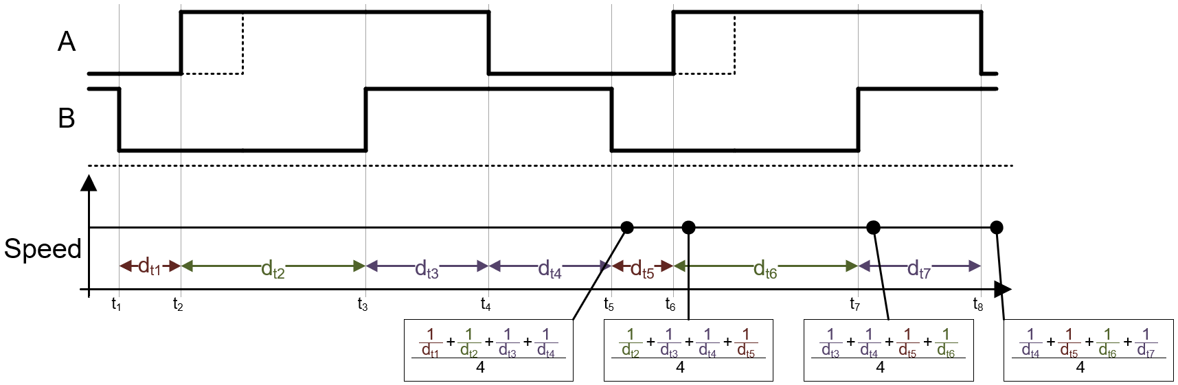
With this setup, the sum of the last 4 elapsed delta times is always the same.
The resulting speed value therefore remains stable.
Quadrature Decoding Input Signals Glitch Filter
In some situations, the simulation environment may be contaminated owing to
cross-talking issues. There are many reasons for this such as weak signal
drivers, long cables for connections, different signal sources, etc. This issue
often leads to the problem of signal glitches and spikes of the measured signals
which can affect the measured results. The QAD code module offers a
parameterizeable glitch filter to improve such environments. The following image
depicts the functionality:
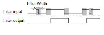
Note that the glitch filter width should not be set higher than required. For
instance if the filter width is higher than the maximum required signal
frequency (e.g. lowest signal width), the measurement results will be
incorrect.