Quadrature - Decoder v3
Quadrature - Decoder v3 — The QAD driver block allows quadrature
encoders to be read.
Library
Simulink Real-Time - Speedgoat
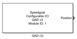
Description
The QAD driver block allows quadrature encoders to be read.
Ports
The width of all the inputs and all the outputs are equal to the channel count as
defined in the channel vector parameter.
Inputs
-
Clear position
Options for the input are:
Note that using this port introduces additional latency.
This port is enabled/disabled using the 'Show clear position input'
parameter.
-
Clear flag index found
Options for the input are:
![[Note]](images/note.png) | Note |
|---|
Using this port introduces additional latency. This port is
enabled/disabled using the 'Show clear flag index found input'
parameter. |
Outputs
-
Position
The position at the moment when the latch occurred. This port is
enabled/disabled using the 'Show latched position output port'
parameter. When parameter 'Interpolate inner position' is enabled, this
output port data type is a double, where the integer part corresponds to
the discrete position (number of transitions detected) and the
fractional part (between x.0 and x.999) is the interpolated distance
done until the latch.
-
Turns
Number of revolutions recorded by the QAD code module (3). The output
is signed, with the sign indicating the direction of movement.
-
rpm
The instantaneous speed determined by the QAD code module (3). Only
able to determine speed of a non static system.
-
Direction
The direction of rotation for the most recently measured position.
Possible values for each vector element are:
0: Counter-clockwise
1: Clockwise
This port is enabled/disabled using the 'Show direction
output' parameter.
-
Index found
Indicates if the C/index position has been reached. Possible values
for each vector element are:
This port is enabled/disabled using the 'Show index
found output port' parameter.
Parameters
Tab: Module setup
-
Configurable I/O Module ID
This parameter associates a code module block with a configurable I/O module setup
block. Set this value to match the Module ID defined in the setup block of the
required configurable I/O module.
-
Channel Vector
A vector of channels this driver block entity will access. You can specify
channels in the range 1-N (N = the number of channels implemented in your specific
configuration file defined in the Setup block). The width of this vector also
defines the subsequent size of some of the following parameters if scalar expansion
applies. With a single block, all the channels of the block are synchronized.
-
Reset positions and flags on startup
When checked, the driver will reset the positions and the flags as
computed during the previous runtime.
-
Sample Time
Defines the base sample time at which this driver block gets its sample hit. This
parameter can also be set to -1 for inherited
sample time. The units are in seconds.
Tab: Quadrature decoder
-
Operating mode
This QAD code module supports the following operating modes: Mode
Resolution Quadrature decoding 1x, 2x, and 4x Direction count 1x, and 2x
Up/down count 2x, and 4x
-
Index control mode
Defines how the QAD code module reacts at each low to high transition
detected on the C/Input I/O line. Supported modes are:
Ignore index input: no action
Reset on index: Counter is reset at every occurrence of a
low to high transition present on C/Index
Index reference mode: Counter is reset to zero at the
first C/Index event detection and Index control mode then
changes to "Ignore index input"
Gate on index: Counter is enabled only when C/Index is
high.
-
Sampling
Sampling resolution. Supported sampling resolutions are:
1x (Quadrature decoding, and direction count only)
2x (All modes)
4x (Quadrature decoding, and up/down count only)
-
Steps per revolution vector
Defines the counting range of the counter. Position output will be in
the range [0, Steps per revolution - 1]. This generates a step if you
turn backwards; for example 3, 2, 1, 0, 16, 15, and so on.
-
Latch mode
Counter latch mode. Options are:
Disabled: No latching
Latch on C/Index: Current counter value is stored into the
position register (latched). The counter value will only be
updated again at the next low to high transition event on
the C/Index line.
Hardware latch: latches counter value read by dedicated
hardware input (D-line).
Software latch: the model latches counter values for all
channels configured with the specific QAD driver
block.
-
Interpolate inner position
When checked, QAD code module (3) will record the duration between A
and B transitions (and between B and A) to interpolate the position
within one segment and which corresponds to the predicted position when
a latch occurs.
-
Swap AB inputs
Allows user to interchange A and B I/O lines.
Tab: Input and output port configuration
-
Show clear position input
Enables/disables the clear position input port, which is used to
dynamically change position values to zero during real-time execution.
Note that enabling this port introduces additional latency. See Input
and output ports section for more information.
-
Show clear flag index found input
Enables/disables the possibility to clear index found flag during
runtime. See Input and output ports section for more information.
-
Show position output
Enables/disables the position output port. See Input and output ports
section for more information.
-
Show turns output
Enables/disables the number of turns output port. See Input and output
ports section for more information.
-
Show speed output
Enables/disables the speed output port to provide rpm information. See
Input and output ports section for more information.
-
Show direction flag output
Enables/disables the direction flag output port. See Input and output
ports section for more information.
-
Show index found flag output
Enables/disables the Index found flag output port. See Input and
output ports section for more information.