Quadrature - Decoder v5
Quadrature - Decoder v5 — The QAD driver block allows quadrature
encoders to be read.
Library
Simulink Real-Time - Speedgoat
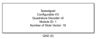
Description
The QAD driver block allows quadrature encoders to be read.
Ports
The width of all the inputs and all the outputs is equal to the channel count as
defined in the Channel Vector parameter.
Inputs
-
Speed Filter Width
This port sets the width of the speed filter. This input is only
visible if the Make Dynamic option of
the Speed Measurement Filter parameter
is set. Valid input for this port is an integer number between 1 and 256
(for details see Quadrature
Decoding Speedfilter)
-
Clear Position
Options for the input are:
This input is only visible if the Show Clear Position Input parameter is set.
-
Clear Index Found Flag
Options for the input are:
![[Note]](images/note.png) | Note |
|---|
Enabling the input ports introduces additional latency. |
Outputs
-
Position [Number of Slot]
This port shows the current position of the decoded signal. The
current slot number is shown. Depending upon the Captured Edges and Extrapolate
Position Output parameters, this output is either an
integer or a fraction between 0 and the number set in the Number of Slots Vector parameter minus 1 (for
details see Quadrature
Decoding). This output is only visible if the Show Position Output parameter is set.
-
Turns
This port shows the number of revolutions recorded by the QAD. The
output is signed, the range is -227 … 0 …
227 -1. The output overflows if the limit
is attained; for example, when rotating forward and the position number
reaches 227 minus 1, the next number will be
-227. This output is only visible if the
Show Turns Output parameter is
set.
-
Speed [RPM]
This output shows the speed in RPM (Revolutions per Minute). The
output is positive when rotating forward (i.e. clockwise) and negative
when rotating backward (i.e. counterclockwise). This output is only
visible if the Show Speed Output
parameter is set.
| Note |
|---|
The detection of the rotation direction is only possible when the
Captured Signal Edges parameter
is set to Captured A + B
Signal. |
-
Speed Valid
This output shows if the Speed [RPM]
output is valid. If the Speed Filter
Width input changes, the Speed
[RPM] output might become invalid. This output is only
visible if the Show Speed Output
parameter is set.
-
Index Found
This output is set high if the C/index position has been detected
once. Possible values for each vector element are:
This output is only visible if the Show Index Found Flag Output parameter is set.
-
Time Since Last Signal Edge [s]
This output shows the time in seconds since the last signal edge was
detected. This output is only visible if the Show
Time Since Last Signal Edge Output parameter is
set.
| Note |
|---|
Enabling the output ports introduces additional latency. |
Parameters
Tab: Module Setup
-
Configurable I/O Module ID
This parameter associates a code module block with a configurable I/O module setup
block. Set this value to match the Module ID defined in the setup block of the
required configurable I/O module.
-
Channel Vector
A vector of channels this driver block entity will access. You can specify
channels in the range 1-N (N = the number of channels implemented in your specific
configuration file defined in the Setup block). The width of this vector also
defines the subsequent size of some of the following parameters if scalar expansion
applies. With a single block, all the channels of the block are synchronized.
-
Sample Time
Defines the base sample time at which this driver block gets its sample hit. This
parameter can also be set to -1 for inherited
sample time. The units are in seconds.
Tab: Quadrature Decoder
-
Number of Slots Vector
The number of slots per revolution (for details see Quadrature Encoding).
-
Captured Edges
Selects which signal edges will be captured:
Capture A + B Signal: Each rising and falling edge of the
QAD A and B signals is used to detect the position and
speed.
Capture A Signal Only: Each rising and falling Edge of the
QAD A signal is used to detect the position and speed. This
setting can be used for single channel sensors. With this
setting, the direction cannot be evaluated
Capture Rising Edges A Signal Only: Only the rising edges
of the QAD A signal are used to detect the position and
speed. This setting can be used for single channel sensors.
With this setting, the direction cannot be evaluated
Capture Falling Edges A Signal Only: Only the falling
edges of the QAD A signal are used to detect the position
and speed. This setting can be used for single channel
sensors. With this setting, the direction cannot be
evaluated
| Note |
|---|
For single channel encoders, this parameter must not
be set to Captured A + B
Signal. The measured values will be wrong
in this case |
-
Extrapolate Position Output
When set, the QAD code module will extrapolate the position (number of
slot) between two detected signal edges. The extrapolation uses the
current measured speed and the time since the last signal edge was
detected. Note that the extrapolation is only 100 % valid if the speed
of the measured signals is constant (for details see Quadrature
Decoding Extrapolate).
-
Swap AB Inputs
When set, the QAD A and B signals are interchanged.
-
Index Control Mode
Defines how the C/Index signal is used by the QAD code module. The
settings are:
Ignore Index: The C/Index signal is completely
ignored
Reset on Index: Counter is reset at every rising edge
occurrence of the C/Index signal
Enable on Index: The complete QAD measurement is only
enabled when C/Index is high
-
Latch Mode
Defines the latch mode. The settings are:
Disabled: the values of all configured channels of the QAD
driver block are latched at model sampling time
Latch on C/Index Input: the values of all configured
channels of the QAD driver block are latched at a rising
edge on the C/Index signal
Latch on D Input: the values of all configured channels of
the QAD driver block are latched at a rising edge on the D
signal
-
Index Signal Gating
Defines how the C/Index signal is passed to the QAD code module. The
settings are:
No Gating: the C/Index signal is directly passed
Gate with A Signal: the C/Index signal is only passed if
the A signal is high
Gate with A + B Signal: the C/Index signal is only passed
if A and B signals are both high
-
Speed Measurement Filter
Each signal edge (configured by the Captured
Signal Edges parameter) generates a new speed value. The
speed values are filtered by a moving average filter on the QAD code
module (for details see Quadrature
Decoding Speedfilter). When the Make
Dynamic parameter is not set, the depth of the filter can
be set with the Filter Width [Number of
Measurements] parameter. In this case the number of
averaged speed values is the same for a complete model run. When the
Make Dynamic parameter is set, the
depth of the filter can be set with the Speed
Filter Width block input signal. In this case the number
of averaged speed values can be changed during model runtime.
-
Input Signals Glitch Filter
Each of the QAD code module input signals passes a glitch filter.
Signal glitches (positive and negative) with a time less than the time
defined by the Filter Width [s] Vector
parameter do not pass. (for details see Quadrature
Decoding Glitchfilter)
| Note |
|---|
Set the glitch filter as low as possible since this parameter also
limits the maximum frequency of the QAD signal to be measured. In
addition, we recommend setting the glitch filter time to a value not
greater than half of the measurable QAD signal pulse time, for
example; if the expected maximum frequency of the QAD signal (the A-
or B-Signal) to be measured is 1 MHz (meaning the QAD signal is 500
ns low and 500 ns high), then the glitch filter should be set to 250
ns or less. |
Tab: Input and Output Port Configuration
-
Show Clear Position Input
When this parameter is set, the Clear
Position input is shown.
-
Show Clear Flag Index Found Input
When this parameter is set, the Clear Index
Found Flag input is shown.
-
Show Position Output
When this parameter is set, the Position [Number
of Slot] output is shown.
-
Show Turns Output
When this parameter is set, the Turns
output is shown.
-
Show Speed Output
When this parameter is set, the Speed
output is shown.
-
Show Index Found Flag Output
When this parameter is set, the Index
Found output is shown.
-
Show Time Since Last Signal Edge Output
When this parameter is set, the Time Since Last
Signal Edge output is shown.