Quadrature - Encoder v3
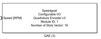
Quadrature - Encoder v3 — The QAE driver block provides the
simulation functionality for a quadrature encoder.
Library
Simulink Real-Time - Speedgoat
Description
The QAE driver block provides the simulation functionality for a quadrature
encoder.
In QAE version 3, the number of slots per revolution can be an integer number
between1 and 226.
In addition, the A and B signals can be configured individually.
Ports
The width of all the inputs and all the outputs is equal to the channel count as
defined in the Channel Vector parameter.
Inputs
-
Speed [Rpm]
This port sets the QAE speed in RPM (Revolutions per Minute). A
positive value results in CW (clockwise) quadrature signals, a negative
value results in CCW (counterclockwise) quadrature signals (for details
see Quadrature Encoding
).
-
Disturb Signal A
This port is only visible if Enable
in the Disturb Signal A parameter is
set. Depending upon the settings of Single and Dismiss High
in the Disturb Signal A parameter, this
input interrupts the quadrature A signal.
-
Disturb Signal B
This port is only visible if Enable
in the Disturb Signal B parameter is
set. Depending upon the settings of Single and Dismiss High
in the Disturb Signal B parameter, this
input interrupts the quadrature B signal.
Outputs
-
Position [Number of Slot]
This port shows the current position of the QAE. This output is an
integer number between 0 and the number set in the Number of Slots Vector parameter minus 1 (for details
see Quadrature Encoding
). This output is only visible if the Show
Position Output Port parameter is set.
-
Slot Position
This port shows the position within the current slot. The output is a
fraction between 0 and 1 (for details see Quadrature Encoding
)and is only visible if the Show Slot
Position Output Port parameter is set.
![[Note]](images/note.png) | Note |
|---|
Using the output ports introduces additional latency. |
Parameters
Tab: Module Setup
-
Configurable I/O Module ID
This parameter associates a code module block with a configurable I/O module setup
block. Set this value to match the Module ID defined in the setup block of the
required configurable I/O module.
-
Channel Vector
A vector of channels this driver block entity will access. You can specify
channels in the range 1-N (N = the number of channels implemented in your specific
configuration file defined in the Setup block). The width of this vector also
defines the subsequent size of some of the following parameters if scalar expansion
applies. With a single block, all the channels of the block are synchronized.
-
Sample Time
Defines the base sample time at which this driver block gets its sample hit. This
parameter can also be set to -1 for inherited
sample time. The units are in seconds.
Tab: Quadrature Encoder
-
Number of Slots Vector
The number of slots per revolution (for details see Quadrature Encoding)
-
Signal A Switch-On Vector [deg]
The phase angle where the Signal A switches on.
-
Signal B Switch-Off Vector[deg]
The phase angle where the Signal B switches off.
-
Signal B Switch-On Vector[deg]
The phase angle where the Signal B switches on.
-
Initial Position Vector
The position of the Encoder at model start. The parameter is only
visible if the configuration file supports QAE v3.3 or newer.
| Note |
|---|
The initial position cannot be higher than the parameter Number of Slots. This parameter is a
fractional number where the number itself represents the slot number
minus one and the fraction represents the position within the slot.
As an example, if the initial position of the encoder shall be in
the middle of the second slot, the initial position must be set to
1.5. In other words, the initial position
is now one and a half slots from the zero-position |
-
Disturb Signal A
If the Enable parameter is set, the
quadrature A signal can be interrupted. The type of interruption depends
upon the following parameters (see also Quadrature
Encoding Interrupt Signals for details):
Dismiss High parameter:
Single parameter:
Set: A rising edge on the Disturb Signal
A input will perform a single dismiss of the
quadrature A signal level which is selected on the Dismiss High parameter described
above
Not Set: Setting the Disturb Signal
A input permanently dismisses the quadrature A
signal level which is selected on the Dismiss High parameter described above
-
Disturb Signal B
Same settings as the Disturb Signal A
parameter but valid for the quadrature B signal.
Tab: Input and Output Configuration
-
Show Position Output Port
When this parameter is set, the Position [Number
of Slot] output is shown.
-
Show Slot Position Output Port
When this parameter is set, the Slot
Position output is shown.