MSCP Usage Notes
MSCP Usage Notes — Usage information about the
MSCP driver blocks
Overview
The MSCP driver blocks allow users to configure and operate the Modular Signal
Conditioning Platform with a Speedgoat real-time target machine. These usage notes
provide information on how to use the MSCP driver blocks in the
Simulink® environment.
Simulink Bus Objects
The MSCP driver blocks use Simulink bus objects. Bus objects for configured MSCP
devices and the modules are exported to the user's workspace when configuring the
setup block.
The bus signals for MSCP devices are named: 'MscpBus' followed
by the network index 'Network_XX', device index
'Device_XX' and 'Read' or
'Write'. For example,
'MscpBus_Network_00_Device_01_Write' is the name of the bus
signal for the write operation of the first MSCP device of network 0. Bus signals
for modules are named: 'MscpBus' followed by the module name.
'Read' or 'Write' is added to modules
where the bus structure of input and output differs. For example:
'MscpBus_SC9203' is the name of the bus signal to use for
write and read operations of an SC9203 module.
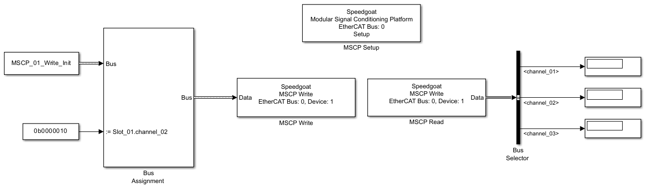
The figure below showcases how to use a Bus Assignment and a Bus Selector block
for the MSCP driver blocks. A constant block with Output Data
Type: 'Bus: MscpBus_Network_00_Device_01_Write' is
connected to the first input of the Bus Assignment block. The value of the constant
block is used to initialize the bus and can either be a struct that matches
hierarchy and attributes of the bus or the value 0. You can generate a struct that
matches hierarchy and attributes of the bus with
Simulink.Bus.createMATLABStruct. For more information about
Simulink Bus Objects, please refer to the MathWorks®
web documentation.
SC2191
- Bus: MscpBus_SC2191_Write
Channel_01, Channel_02, […], Channel_16
Configuration. Unit: Ohm. Data type:
uint8*
Vlow. Unit: Volt. Data type: single
Vhigh. Unit: Volt. Data type: single
- Bus: MscpBus_SC2191_Read
Channel_01, Channel_02, […], Channel_16
*
SC4101-100-0.1
- Bus: MscpBus_SC4101_100_0_1
Channel_01, Channel_02, […], Channel_08
*Resistance between 0 and 102.3 Ohm with a
0.1 Ohm resolution. Values below 0 or above 102.3 Ohm will default to
102.3 Ohm.
SC4191-5110k-10k
- Bus: MscpBus_SC4191_5110k_10k
Channel_01
*Resistance between 0 and 5110 kOhm with a
10 kOhm resolution. Values below 0 will result in infinite resistance (open
circuit) and values above 5110 kOhm will default to 5110 kOhm.
SC9201
- Bus: MscpBus_SC9201
Channel_01, Channel_02, […], Channel_08
*The switch state of one channel is stored as a uint8
value. Zero indicates that the relay is open; one indicates that the relay is
closed.
SC9203
- Bus: MscpBus_SC9203
Channel_01, Channel_02, […], Channel_12
*The switch state of one channel is stored as a uint8
value. Zero indicates that the relay is open; one indicates that the relay is
closed.
SC9203-FIU
- Bus: MscpBus_SC9203_FIU
Channel_01, Channel_02, […], Channel_12
*The switch state of one channel is stored as a uint8
value. Zero indicates that the relay is open; one indicates that the relay is
closed.
**The fault state of one channel is stored as a uint8
value. Zero indicates that the relay is open; one indicates that the relay is
closed.
SC9205
- Bus: MscpBus_SC9205
Channel_01, Channel_02, […], Channel_12
*The switch state of one channel is stored as a uint8
value. Zero indicates that the relay is open; one indicates that the relay is
closed.
SC9205-FIU
- Bus: MscpBus_SC9205_FIU
Channel_01, Channel_02, […], Channel_12
Switch state. Data type:
uint8*
Fault state 1. Data type:
uint8**
Fault state 2. Data type:
uint8***
*The switch state of one channel is stored as a uint8
value. Zero indicates that the relay is open; one indicates that the relay is
closed.
**The fault state 1 of one channel is stored as a uint8
value. Zero indicates that the relay is open; one indicates that the relay is
closed.
***The fault state 2 of one channel is stored as a
uint8 value. Zero indicates that the relay is open; one indicates that the relay is
closed.
SC9502-SPDT-TTL
- Bus: MscpBus_SC9502_SPDT_TTL
Channel_01, Channel_02, […], Channel_16
*The switch state of one channel is stored as a uint8
value. Zero indicates that the relay is open; one indicates that the relay is
closed.
SC9503-SPST-TTL
- Bus: MscpBus_SC9503_SPST_TTL
Channel_01, Channel_02, […], Channel_08
*The switch state of one channel is stored as a uint8
value. Zero indicates that the relay is open; one indicates that the relay is
closed.
SC9601
- Bus: MscpBus_SC9601
Channel_01, Channel_02, […], Channel_12. Data type:
uint8*
Termination. Data type:
uint8*
Fault Insertion. Data type:
uint8*
* The switch state is stored as a uint8 value. A
value of zero indicates that the relay coil is de-energized; a value of one
indicates that the relay coil is energized. The resulting contact state depends on
whether the relay is configured as normally open (NO) or normally closed (NC). For
example, a value of one closes the contact for an NO relay, but opens the contact
for an NC relay.
SC9601 Termination Bit Map
SC9601 Fault Insertion Bit Map