IO753 Usage Notes v2
IO753 Usage Notes v2 — Usage information about the
I/O module
Description
This section provides further information about how to configure the IO753 Modbus
TCP Client module.
Front Plate Description
IO753 PCI and PCIe modules
The IO753 acts as one Modbus TCP Client exclusively. The two RJ45 connectors
simply serve to build up a line-based network structure. Plug the cable from the
previous Modbus TCP Server into the first socket. Connect the second socket with
the next Modbus TCP Server. The LEDs described below indicate the communication
status of the single Modbus TCP Client.
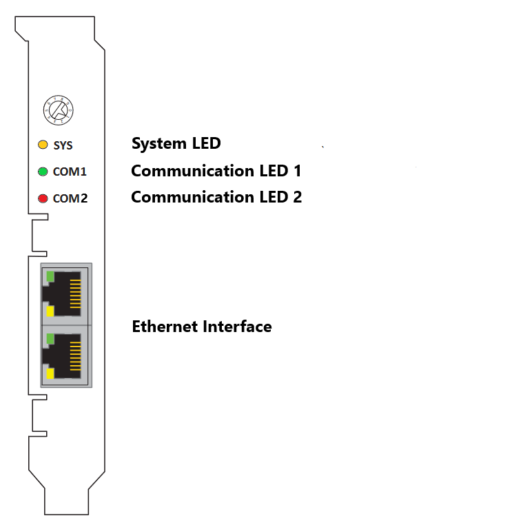
The rotary switch has no functional role.
IO753 mPCIe module
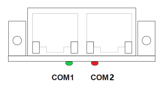
Note that in some real-time target machines,
the mPCIe module is reversed; that is, the Error LED appears on the right.
LED Status Description
Note that only the IO753 PCI and PCIe modules have the SYS LED. This LED does not
feature on the IO753 mPCIe module.