IO753 - Setup v2
IO753 - Setup v2 — Configure the IO753 I/O
module
Library
Simulink Real-Time - Speedgoat
Description
The Setup block configures the protocol stack of the related I/O module and
enables the send and receive blocks to exchange data on the network.
![[Caution]](images/caution.png) | Caution |
|---|
This block is only supported by MATLAB from R2019b. |
Ports
This driver block has no input or output ports.
Parameters
Tab: General
- Module ID
The Module ID has two functions:
It logically connects the Setup block and its I/O blocks
It also informs the auto-search feature of the PCI Slot parameter. If only
one I/O module of this family is installed, the Module ID must be set to
1. To see how each I/O module maps to a
Module ID, use this Speedgoat API:
speedgoat.getIoInterfaces("TargetName", "mySpeedgoat")
This Setup block belongs to two families of I/O modules that use the same hardware
for multiple protocols. Across both families, the Module ID must be unique.
IO64X/IO75X (single-node modules): IO641,
IO642, IO643, IO644, IO750, IO751, IO752, IO753, IO754, IO755, IO756,
IO758
IO64X-32/IO75X-32 (multi-node modules):
IO642-32, IO752-32, IO754-32, IO756-32
If the PCI Slot parameter is set to -1
(auto-search), the Module ID must be in the range 1:n, where 'n' cannot be larger
than the number of modules of this type installed in the target machine. Not all
installed I/O modules need to be used.
To use this Setup block with a multi-node I/O module (IO75X-32 family), the Module
ID must be defined as a two-element vector. The second vector element is the
sub-module ID. It describes the specific node (1:32) within the I/O module. The 32
nodes are internally connected to form two linear networks (daisy-chain), where the
first and the last node of both chains are externally accessible. If one node is not
configured (has no Setup block), the chain terminates at this point. The sub-module
IDs must therefore start at node 1, 16, 17 or 32 and not have any gaps.
![[Note]](images/note.png) | Note |
|---|
When using I/O modules of both families simultaneously (single-node and
multi-node I/O modules), always use explicit addressing in the PCI Slot parameter. Ignore the Module IDs returned by
the getIoInterfaces function and instead assign unique Module IDs accross all
modules used. |
-
PCI Slot (-1: auto-search)
There are two approaches for mapping the block to a specific I/O
module installed in your target machine. All modules of the same
family (see Module ID above) must be configured using the same
method.
- Auto-Search: with the default value -1 the I/O module will be
automatically located in the target machine. If you have
multiple modules of the same family, the Module ID defines
which module is associated with this block. To see how each
I/O module maps to a Module ID, use this Speedgoat API:
speedgoat.getIoInterfaces("TargetName", "mySpeedgoat") - Explicit Addressing: to explicitly define the logical
address of the I/O module in the target machine, you can
provide the PCI bus and slot numbers as a vector: [bus,
slot]. To determine these numbers, run the following command
in the MATLAB command window:
speedgoat.getIoInterfaces("TargetName", "mySpeedgoat", "Advanced", true)Note
that the PCI address can change whenever an I/O module is
added or removed. Usually, auto-search is the best
option.
- Bus Start
Automatic: The device starts the communication immediately after the
initialization of the real-time application on the target. The
communication is maintained even if the real-time application stops.
Application controlled: After initialization of the real-time
application on the target, the communication of the slave with the
network is off. The device starts the communication immediately after
the real-time application has been started. The device stops the
communication on the network when the real-time application stops.
-
IP Address
Only available if "BootP" and "DHCP" are not set.
-
Netmask
Only available if "BootP" and "DHCP" are not set.
-
Gateway
Only available if "BootP" and "DHCP" are not set.
-
BootP
If set, the device obtains its IP Address, Netmask and Gateway Address
from a BOOTP server.
-
DHCP
If set, the device obtains its IP Address, Netmask and Gateway Address
from a DHCP server.
Tab: Modbus Commands
- Swap Registers
The bytes of a value must be swapped if the sender and the receiver
interpret the byte order in different ways (little-endian versus big-endian).
The Speedgoat real-time target machine uses little-endian. If
the swap option is enabled, all register values from the application
context will be swapped before they are sent to the network. All
received register values from the network will be swapped before they
are submitted to the application context. The swap option only affects
input registers and holding registers (transmitted by function codes
FC3, FC4, FC6, FC16). Discretes and coils are not affected. Use Byte
Reversal blocks instead of enabling the global byte swapping if only
single registers need to be swapped.
- Delay
This delay time specifies a fixed time that is inserted between two
commands of the command table. It can be used to delay the execution of
commands, for example, for a slow server that needs to pause on each
request.
- Command Table
This table defines the read and write requests the Modbus client
protocol stack performs during model execution. Use the buttons to add,
move or delete commands. The number of commands is limited to 256. The
I/O module has its own internal process data memory which allows the
communication on the Modbus network to occur separately from of the
real-time application. Use the Send and Receive blocks to access the
process data of the I/O module.
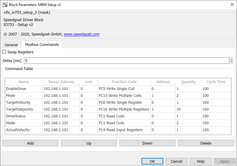
Command properties
Name: The command name is
optional and is just used for labeling the ports of the Send
and Receive blocks
Server Address: The IP
address of the Modbus server whose data will be read or
written by the command. The number of servers is limited to
16. Commands related to the same server must be consecutive
in the table
If the Modbus server is a ModbusRTU - ModbusTCP gateway,
you must assign one unit id for each Modbus RTU server
behind the gateway. Leave 0 if your application does not
handle Modbus RTU at all
Enter the Function Code
of the command. There are codes for reading and writing
either bits (discrete inputs, coils) or words (input
registers, holding registers):
FC1 (Read Multiple Coils)
FC2 (Read Multiple Discrete Inputs)
FC3 (Read Multiple Holding Registers)
FC4 (Read Multiple Input Registers)
FC5 (Write Single Coil)
FC6 (Write Single Holding Register)
FC15 (Write Multiple Coils)
FC16 (Write Multiple Holding Registers)
Depending on the function code, each command
invokes one port either on the Send or on the Receive block.
A Modbus server usually manages 4 data areas:
Coils: readable and writeable bit
values
Discrete Inputs: readable bit values
Holding Registers: readable and writeable word
values (2 bytes)
Input Registers: readable word values (2
bytes)
The function code specifies the target area
of the command. The Address
of the command is the address of a particular value within
this area. Depending on the function code, the address is
either bit-based or word-based.
The Quantity defines the
number of values to be read or written per request. It is
either a number of bits or a number of words
Each command can be configured with an individual
Cycle Time. This time
specifies the execution cycle of the command. The maximum
value is 60000 ms. For write commands, a cycle time less
than 0 causes the I/O module to process the command (transmit the message) only if at least one related value changes (the signal connected to the corresponding input port of the IO753 Send block changes).