Documentation search search close
CONTENTS
https://www.speedgoat.com/help/slrt/page/icon_documentation.jpg
v10.0.1.x for R2026a
View other versions

IO644 Usage Notes v2

IO644 Usage Notes v2 — Usage information about the I/O module

Description

This section provides additional information about the IO644 CANopen Slave module.

EDS File

To set up CANopen communication, you must import the electronic data sheets (EDS) of the CANopen slave devices into your CANopen Master configuration tool or PLC programming tool. Speedgoat does not provide a default EDS file for the IO644. Instead, you can export an EDS file from the IO644 Setup block that is specific to your Simulink model.

For simulation purposes, you can import EDS files from other vendors and autogenerate a communication interface in Simulink ready for use with the IO644. The createFromEds function places the IO644 Setup, PDO, and Object driver blocks into the model and automatically sets the block parameters according to the objects defined in the EDS file.

Communication Object Identifier (COB ID)

With CANopen, each information shared on the network is a COB (Communication Object) and has a COB ID (Communication Object Identifier). The COB ID includes the unique 11-bit CAN ID and additional information. This CAN ID ranges from 0 to 2047. The CANopen standard defines the following CAN ID ranges:

CAN IDDescription
0Network Management (NMT)
1Reserved
128SYNC
129-255Emergency
256Timestamp
257-384Safety
385-511TxPDO 1
513-639RxPDO 1
641-767TxPDO 2
769-895RxPDO 2
897-1023TxPDO 3
1025-1151RxPDO 3
1153-1279TxPDO 4
1281-1407RxPDO 4
1409-1535TxSDO
1537-1663RxSDO
1760Reserved
1793-1919NMT Error Control
2020-2047Reserved

Pre-defined Objects

Some objects in the object dictionary are mandatory for the basic operation of the I/O module. These objects are automatically created according to the parameters of the Setup and PDO blocks, and must not be added by Object blocks.

ObjectSub-objectNameValue
1000 Device TypeSetup block; Device Type parameter
1001 Error Register0
1005 COB-ID Sync0x80
1006 Communication Cycle Period0
1007 Synchronous Window Length0
100C Guard TimeSetup block; Guard Time parameter
100D Life Time FactorSetup block; Life Time Factor parameter
1012 COB-ID Time Stamp0x00000100
1014 COB-ID EMCY0x80 + CAN Node ID
1016 Consumer Heartbeat Times 
10161 to 40Consumer Heartbeat TimeSetup block; Consumer Time parameter
1017 Producer Heartbeat TimeSetup block; Producer Time parameter
1018 Identity Object 
10181Vendor IDSetup block; Vendor ID parameter
10182Product CodeSetup block; Product Code parameter
10183Revision NumberSetup block; Revision Number parameter
10184Serial NumberSetup block; Serial Number parameter
1029 Error Behaviour 
10291Communication Error0
10292Internal Device Error1
1200 Server SDO Parameter 
12001COB_ID Client->Server(rx)0x600 + CAN Node ID
12002COB_ID Server->Client(tx)0x580 + CAN Node ID
1400 to 15FF Receive PDO Parameter0x1400 refers to the first Rx PDO block, 0x1401 to the second, and so on
1400 to 15FF1COB-IDPDO block; COB ID parameter
1400 to 15FF2Transmission TypePDO block; Transmission Type and Rate parameters
1600 to 17FF Receive PDO Mapping0x1600 refers to the first Rx PDO block, 0x1601 to the second, and so on
1600 to 17FF1 to 8PDO Mapping EntryPDO block; Mapping parameter
1800 to 19FF Transmit PDO Parameter0x1800 refers to the first Tx PDO block, 0x1801 to the second, and so on
1800 to 19FF1COB-IDPDO block; COB ID parameter
1800 to 19FF2Transmission TypePDO block; Transmission Type and Rate parameters
1800 to 19FF3Inhibit TimePDO block; Inhibit Time parameter
1800 to 19FF5Event TimerPDO block; Event Timer parameter
1A00 to 1BFF Transmit PDO Mapping0x1A00 refers to the first Tx PDO block, 0x1A01 to the second, and so on
1A00 to 1BFF1 to 8PDO Mapping EntryPDO block; Mapping parameter

Front Plate Description

IO644 PCI and PCIe modules
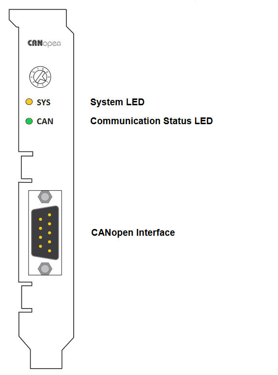
The rotary switch has no functional role.

IO644 mPCIe module
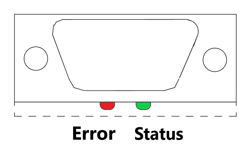
Note that in some real-time target machines, the mPCIe module is reversed; that is, the Error LED appears on the right.

LED Status Description

PCI and PCIe modules
LEDColorStateMeaning
SYSGreenOnOperating system running
 Green/YellowBlinkingSecond stage bootloader is waiting for firmware
 YellowOnBootloader netX (= romloader) is waiting for second stage bootloader
 OffOffPower supply for the device is missing or hardware defect
CANGreenOnThe device is in the OPERATIONAL state
 GreenBlinking (2.5 Hz)The device is in the PREOPERATIONAL state
 GreenSingle flash The device is in the STOPPED state
 Red/GreenFlickering (10 Hz)The Device is in the auto baud rate detection mode
 RedSingle flash Warning limit reached: At least one of the error counters of the CAN controller has reached or exceeded the warning level (too many error frames)
 RedDouble flashError control event: A guard event (NMT slave or NMT master) or a heartbeat event (heartbeat consumer) has occurred
 RedOnThe CAN controller is in bus OFF state
 OffOffThe device is executing a reset or the device has no configuration
mPCIe module
LEDColorStateMeaning
STATUS/COM1GreenOnThe device is in the OPERATIONAL state
 GreenBlinking (2.5 Hz)The device is in the PREOPERATIONAL state
 GreenSingle flashThe device is in STOPPED state
 GreenFlickering (10 Hz, alternatively with ERROR LED)The Device is in the auto baud rate detection mode
 OffOffThe device is executing a reset or the device has no configuration. Refer to the ERROR LED
ERROR/COM2OffOffRefer to the STATUS LED
 RedFlickering (10 Hz, alternatively with STATUS LED)The Device is in the auto baud rate detection mode
 RedSingle flashWarning limit reached: At least one of the error counters of the CAN controller has reached or exceeded the warning level (too many error frames)
 RedDouble flashError control event: A guard event (NMT slave or NMT master) or a heartbeat event (heartbeat consumer) has occurred
 RedOn The CAN controller is in bus OFF state

Status Codes

For the list of status codes, please refer to Status Codes for Protocols Supported with the IO64x/IO75x Modules.