IO644 - Network Status v2
IO644 - Network Status v2 — Outputs the module's NMT
state, allows the state to be changed, and provides extended diagnostics.
Library
Simulink Real-Time - Speedgoat
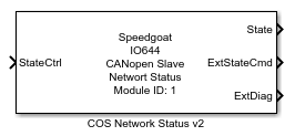
Description
The Network Status block outputs the module's CANopen NMT (Network Management)
state. The states are:
Stopped
Initialization
Pre-operational
Operational
State changes are usually commanded by the remote master node.
However, the block can also set the state in a local manner. This allows the user to
overwrite remote state commands or set the node to Operational state if no external
node sends the required NMT messages. Furthermore, the block outputs internal stack
information and signs of life of other CANopen nodes in the network.
Ports
Outputs
- State,
Outputs the module's current NMT state. The values are:
Data type: uint32
scalar
-
ExtStateCmd
Outputs the state commanded by external nodes (master node).
Data type: uint32
scalar
-
ExtDiag
Provides further information about internal states and errors.
Data type: uint32
vector
The Flags element is encoded as follows:
- Monitoring
Outputs the heartbeat and guarding information for the nodes in the
network for which monitoring is activated in the Setup block. The signal
is a vector of 128 elements. Elements 2 to 128 contain heartbeat
information for the nodes 1 to 127. Element 1 contains the life-guarding
information about the master. The values are:
Data Type:
numeric vector
Inputs
-
StateCtrl
The NMT state the module should reach. See the State output port for possible values. The block tries
to set the state only if the input changes. If a state cannot be
reached, the block will not try again. Instead, the user must provoke a
signal change on the input port.
Parameters
-
Module ID
This ID defines the link to the corresponding Setup block
-
State Control
If selected, the block shows the StateCtrl input port. Otherwise, the port is hidden.
-
External State Command
If selected, the block shows the ExtStateCmd output port. Otherwise, the port is hidden.
-
Extended Diagnostics
If selected, the block shows the ExtDiag output port. Otherwise, the port is hidden.
-
Monitoring
If selected, the block shows the Monitoring output port. Otherwise, the port is hidden.
-
Sample Time
Defines the base sample time at which this driver block gets its sample hit. This
parameter can also be set to -1 for inherited
sample time. The units are in seconds.
![[Caution]](images/caution.png) | Caution |
|---|
All blocks that interface with the same I/O module must have identical
sample times. |