IO624 Usage Notes
IO624 Usage Notes —
Usage information about the I/O module
PSI5: Sensor-to-ECU Communication
The Peripheral Sensor Interface (PSI5) uses two unshielded wires for both power
supply and data communication. The sensor data is transmitted by current modulation
on the supply lines and the data are coded with Manchester coding.
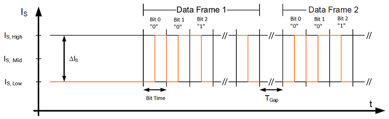
PSI5 provides synchronous and asynchronous data transmission and supports
time-multiplexed multi-channel operation modes for sensor clusters.
In asynchronous operation mode, each sensor is connected to the ECU by two lines
and transmits its data periodically. The timing and repetition rate of the data
transmission is controlled by the sensor.
Synchronous operation mode allows communication timing control by the ECU. This
mode is optional for point-to-point configurations but is mandatory for bus modes.
Timing and access control are implemented using two different voltage levels
generated by the ECU.
In the Setup block Channel X tab, a message
appears in the PSI5 Data Frame section. Data Frame Duration + Time Gap displays the data frame
duration plus a time gap (TGap). A minimum TGap longer than one maximum bit time is
required between two successive data frames. Please bear this value in mind when you
are creating your data frames.
PSI5: ECU-to-Sensor Communication
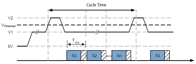
The data transmission period is initiated by a voltage synchronization signal from
the ECU to the sensors (V2). After receiving the synchronization signal, each sensor
starts transmitting its data.
ECU-to-sensor data frames are applied in different ways for the two different bit
coding methods in use: the Tooth Gap or Pulse Width method. To ensure safe data
recognition, combined use of the bit coding method and the respective frame types of
each method is not permitted. Refer to the documentation for the Peripheral Sensor Interface
for Automotive Applications for more information.
Tooth Gap Method
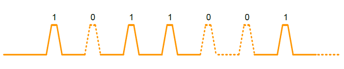
A logical “1” is represented by the presence of a regular (“short”) sync signal
(Signal Sustain Voltage (Vth) = V1 + 2.5[v]
min., pw = 35 [μs] max.), and a logical “0” by the absence of the sync signal during
the expected time window (Cycle Time) of the sync signal period. The voltage for a
logical “0” must remain V1.
Pulse Width Method
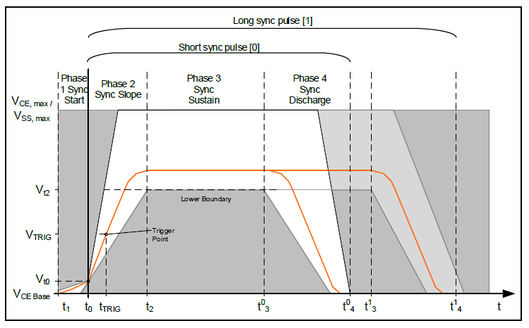
A logical “0” is represented by the presence of the regular (“short”) sync signal
(Signal Sustain Voltage (Vth) = V1 + 2.5[v]
min., pw = 35 [μs] max.), and a logical “1” by a longer sync signal (Signal Sustain Voltage (Vth) = V1 + 2.5[v] min., pw = 62
[μs] max.).

Only synchronization pulses within the permitted time window are
recognized.
Sync Signal Specification
Make sure that the sync signal meets the following specifications:
PSI5-A (Asynchronous)
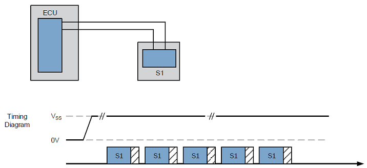
PSI5-A describes a point-to-point connection for unidirectional, asynchronous data
transmission. Each sensor is connected to the ECU by two wires. After switching on
the power supply, the sensor starts transmitting data to the ECU
periodically.
PSI5-U/P (Synchronous Universal/Parallel)
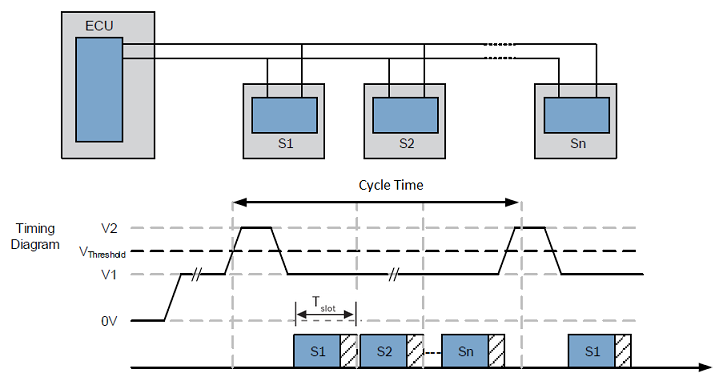
The synchronous operation modes work according to the TDMA (Time Division Multiple
Access) method.
Basic PSI5 Bus Topology
The sensor data transmission is synchronized by the ECU using voltage modulation.
Each data transmission period (Cycle time) is initiated by a voltage synchronization
signal from the ECU to the sensors. After receiving the synchronization signal, each
sensor starts transmitting its data with the time shift (Slot
Delay) in the corresponding time slot.
PSI5-D (Synchronous Daisy Chain)
The PSI5-D operation mode works by synchronous data transmission of one or more
sensors connected in a daisy chain configuration to a single interface of the
transceiver within the ECU. The communication between ECU and sensors is
bidirectional. The sensors must have allocated addresses during startup.
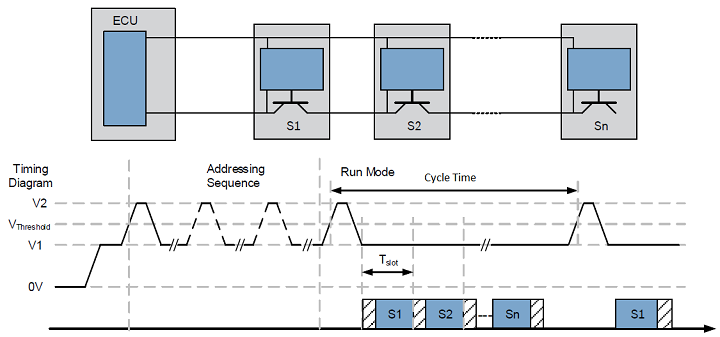
In daisy-chain configuration, the sensors have no fixed address and can be
connected to each position on the bus. During startup, each sensor receives an
individual address and then passes the supply voltage to the following sensor
subsequently. The allocation of addresses is implemented using bidirectional
communication from the ECU to the sensor using a specific sync signal pattern. Once
the individual addresses have been allocated, the sensors start to transmit data in
their corresponding time slots in the same way as specified in the PSI5-U/P bus
topology.
A time gap of 8 [μs] is set at the end of the cycle time because the sync pulse
slope can affect the last bit transmitted. A time gap of 24 [μs] is set at the
beginning of the cycle time because the sync pulse will produce current ripples that
can affect the first bit transmitted. Please bear in mind that the use of the total
cycle time will be reduced by 32 [μs] due to the beginning and end time gap.
ECU-to-Sensor Communication with Tooth Gap
Method
The Tooth Gap method is limited to the use of data frame formats 1–3. Frame format
1–3 is composed of 3 start bits, a data field, and a 3-bit CRC. The start condition
for an ECU-to-sensor communication consists of either at least 5 consecutive logical
zeros or at least 31 consecutive logical ones. The sensor responds with the standard
sensor-to-ECU current communication in its corresponding time slot. This
communication may be sent in data range format within the following two or three
sync periods.
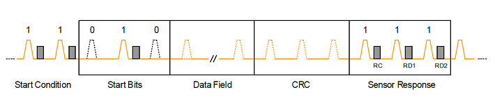
The data field in Frame 1–3 contains a 3-bit sensor address and a 3-bit function
code (FC). For frames 2 and 3, the data field also contains RAdr and Data, the
number of bits is:
Frame 2a "Long" (4-Bit Data Nibbles), 6-bit RAdr, and 4-bit Data.
Frame 2b "Long" (8-Bit Data Word), 2-bit RAdr, and 8-bit Data.
Frame 3 "XLong", 8-bit RAdr, and 8-bit Data.
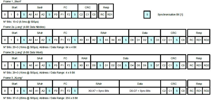
The Synchronization bits (logical “1”) are introduced from the ECU at each 4th-bit
position to ensure differentiation between data content and start condition and to
enable sensor synchronization when using the tooth gap method. This bit is used
internally for the IO624 and is not added to the final output channel data in the
Sync Pulses block.
ECU-to-Sensor Communication with Pulse Width
Method
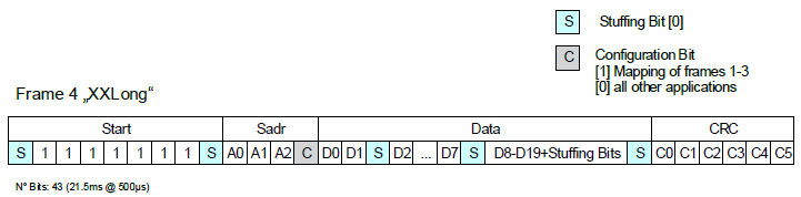
The Pulse Width method uses frame format 4. Frame format 4 is composed of 9 start
bits, a data field, and a 6-bit CRC.

The Data field contains a 3-bit sensor address field, a configuration bit, and
20-bit data containing application-specific information. The Data Field output from
the Sync Pulses block will contain the 20-bit data field.
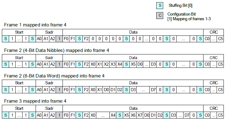
The Data field in Frame 4 can also be composed of all function codes and frame
data content of frame formats 1–3 as described in the Tooth Gap method.
The Stuffing bits (logical “0”) are introduced from the ECU at each 7th-bit
position (8-bit position for start region) to ensure differentiation between data
content and frame start. The Stuffing and Configuration bits are used internally for
the IO624 and are not added to the final output channel data in the Sync Pulses
block.
Principle of Operation
ECU applies supply voltage to PSI5 module (power on)
Wait for supply settling time
ECU assigns sensor address for time slot “TSi” to the next sensor that
has not yet received its configuration
Addressed sensor responds by sending its internal status (acknowledge
or error) message and address confirmation. The sensor closes the
daisy-chain switch to supply next sensor
Repeat steps 2, 3 and 4 until all sensor addresses have been
successfully assigned (from TSn down to TS1)
ECU to send RUN broadcast instruction to start runtime mode
All sensors to send out their initialization data within their
assigned timeslot
All sensors to send out "sensor_OK" messages
All sensors to send out their sensor data
PSI5-V (Variable Time Triggered Synchronous)
The Variable Time Triggered Synchronous operation mode works similarly to
Synchronous mode.
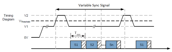
The sensor data transmission is synchronized by the ECU using Pulse Width method.
Each data transmission is initiated by a voltage synchronization signal from the ECU
to the sensors with variable delays. After receiving the synchronization signal,
each sensor starts transmitting its data with the time shift (Slot Delay) in the corresponding time slot.
Wheel Speed Sensor Protocol
Standard 2-level wheel speed sensor with Square Wave “Speed
Protocol"
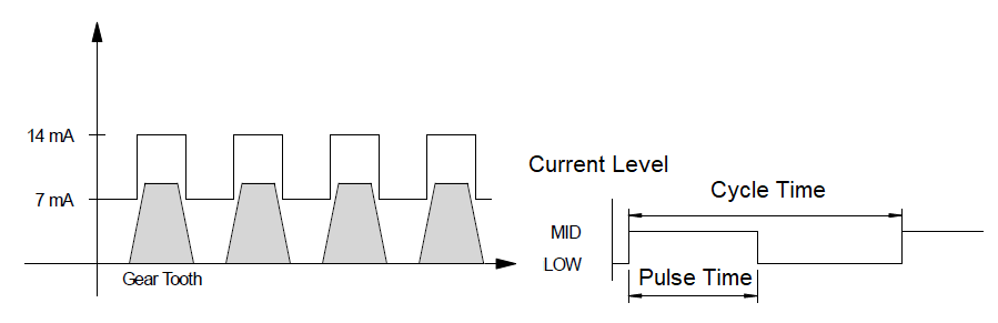
For every gear tooth, a 14 mA rotation signal is sent. The pulse duration
increases with lower rotation speed; this results in a 2-level encoding that is
based on a duty cycle setting:
Speed Protocol / Duty Cycle Diagram
PWM
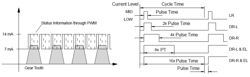
PWM Wheel Speed Sensors transmit additional information by varying the length of
the speed pulses. PWM encoding is based on the Pulse Time parameter and all pulse
widths are derived from this value. PWM-encoded 2-level sensors, with support for
airgap warning (LR), assembly position (EL) and direction of rotation
(DR-R/L)
PWM Diagram
A “zero speed” or “stand still” indication is usually done with pulses of 32 x
pulse time length and with an appropriate large gap (Cycle time = 0.5 – 2 [ms]).
When the cycle time is smaller than the basic pulse width, the pulse is truncated.
When the cycle time has elapsed, a low pulse with the length of the pulse time will
be sent, followed by the next high pulse.
AK-Protocol or VDA
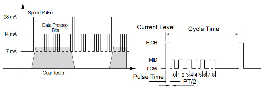
AK-Protocol or VDA uses three current levels and transmits a 9-bit status word
after the Speed Pulse. The VDA encoding starts with a “Speed Pulse” with a High
current level, followed by a short gap, and the Manchester-encoded protocol bits
with Mid current levels.
AK-Protocol / VDA Diagram