IO624 - Send
IO624 - Send —
Sends sensor data frames
Library
Simulink Real-Time - Speedgoat
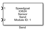
Description
Your model can contain up to eight Send blocks for each I/O module in your target
machine.
To support the sensor-to-ECU communication, the Sensor Send block offers the data
frame FIFO, which holds up to 33 Data Frames.
Ports
Inputs
-
X (X is the send channel number)
Payload that is transferred in a data frame from the sensor to the
ECU. The payload must include the parity or CRC bits. The bits are
transmitted in ascending order, starting with bit 0. The configured
payload length is in 32-bit words.
When PSI5-D (Synchronous Daisy Chain)
is selected in the Setup block, the Send block needs as input the
following data for the selected channel(s):
Data Type:
uint32
Outputs
-
X (X is the send channel number)
When PSI5-D (Synchronous Daisy Chain)
is selected in the Setup block and Outputs
Channels Status Ch X is selected in the Channels Settings tab of the Send block, the
Send block provides the following status information for the selected
channel(s):
0 - No status message
1 - Sensor address is already used
2 - Sensor address received from the ECU is higher than
the max possible number of slots
3 - Channel is programmed with the sensor address in the
corresponding slot.
4 - The last sensor address 1 has been received and
programmed
5 - Channel is relocated with the new sensor
address
6 - Channel will not fit in the next slot
7 - Channel was disabled due to sensor address 1 was
programmed to another channel
Data Type:
double
Parameters
Main Tab
-
Module ID
This ID defines the link to the corresponding Setup block
-
Sample Time
Defines the base sample time at which this driver block gets its sample hit. This
parameter can also be set to -1 for inherited
sample time. The units are in seconds.
Channels Settings Tab
The configuration details are all defined in the Setup block.
-
Outputs Channels Status
During the allocation of the time slot for PSI5-D, the Send block
provides status information for the selected channel. Choose the active
channels by selecting the corresponding checkboxes. The values and the
corresponding information are described in the Outputs section above.
The channels available are defined by selecting PSI5-D (Synchronous Daisy Chain) in the Setup block, and
then selecting the corresponding channels in the Inputs Active Channels parameter.
-
Inputs Active Channels
Choose the active channels by selecting the corresponding checkboxes.
The channels available depend on if the same channels have also been
enabled in the Setup block.