IO624 - Sync Pulses
IO624 - Sync Pulses — Reads sensor synchronous
pulses
Library
Simulink Real-Time - Speedgoat
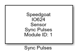
Description
Your model can only contain one of these blocks for each I/O module in your target
machine.
When PSI5-U/P (Synchronous without Daisy Chain)
is selected in the Setup block, the Sync Pulses block reads the synchronous pulses
of the corresponding channel.
When PSI5-D (Synchronous Daisy Chain) is selected
in the Setup block, the Sync Pulses block reads the synchronous pulses of the
corresponding channel and decodes the information that the sync pulses contain. The
frame data content reads from the ECU can be read through the outputs ports for the
specified channel selected in the Setup block.
Ports
This driver block has n uint32-type(f) scalar output ports, where n is the number
of selected channels in the Setup block and f is the number of data items selected
in the Channel Data tab of the Sync Pulses block.
Each port (signal) returns the data in frame format and in the order the data have
been selected.
Outputs
-
X (X is the sync channel number)
The following data are obtained from sync channel X:
-
Sync Pulses
The following two data frames are obtained if the following is
selected in the Setup block: ECU to Sensor
Communication > Pulse Width Method:
The following two data frames are obtained if the following is
selected in the Setup block: ECU to Sensor
Communication > Tooth Gap Method:
Data Type:
uint32
-
Start Bits
Contains the Start data from the ECU. The start bits of frame 1
"Short" format in Tooth Gap method must be [0 1 0] or 2, and in Pulse
Width method must be [1 1 1 1 1 1 1] or 127.
Data Type:
uint32
-
Sensor Address
Contains the sensor address data from the ECU. The address of an
unprogrammed sensor is zero at the beginning.
Data Type:
uint32
-
Function Codes
Contains the function code (FC) data from the ECU.
Data Type:
uint32
-
Data Field
Contains the data frame from the ECU. In frame 1 "Short" format: the
data frame content, the sensor address, and the FC. The first three bits
are the sensor address [A2 A1 A0] and the next three bits the FC [F2 F1
F0]. The broadcast instruction is represented by an address [1 1 1] or
7. The ECU sends the RUN broadcast instruction, which can be read in the
Data Field.
In Frame 2a "Long" (4-Bit Data Nibbles), Frame 2b "Long" (8-Bit Data
Word) and Frame 3 "XLong" format: the data frame content, the sensor
address, the FC, the RAdr and the Data. The number of bits in sensor
address and FC is the same for all the frames as in frame 1. In Frame 2a
the RAdr is 6 bits and Data 4 bits, in Frame 2b the RAdr is 2 bits and
Data 8 bits, and in Frame 3 RAdr and Data are 8 bits.
Data Type:
uint32
-
CRC
Contains the cyclic redundancy check (CRC) data from the ECU. Refer to
the documentation for the Peripheral Sensor Interface for Automotive
Applications chapter 3.3.2 for more information. In Tooth Gap
method CRC is 3 bits, and in Pulse Width method 6 bits.
Data Type:
uint32
-
Data Frame Status
The following values are obtained from Data Frame Status for Tooth Gap
method or Pulse Width method:
0 - No Data Frame Status message
1 - Start Bits OK
2 - Wrong Start Bits. Restart data frame
transmission
3 - Waiting for Sensor Address to be assigned
4 - Broadcast Message received. Start runtime mode
5 - Sensor Address assigned!
6 - No Sync Bits (Tooth Gap method) or Stuffing Bit (Pulse
Width method) during reception of the data frame. Restart
data frame transmission
7 - Frame 1 "Short" detected
8 - Frame 2a "Long" (4-Bit Data Nibbles) detected
9 - Frame 2b "Long" (8-Bit Data Word) detected
10 - Frame 3 "XLong" detected
Data Type:
uint32
The following two data frames are obtained if the frame 2a, 2b, or 3
is detected
-
RAdr
Contains the RAdr data from the ECU.
Data Type:
uint32
-
Data
Contains the Data information from the ECU.
Data Type:
uint32
Parameters
Main Tab
-
Module ID
This ID defines the link to the corresponding Setup block
-
Sample Time
Defines the base sample time at which this driver block gets its sample hit. This
parameter can also be set to -1 for inherited
sample time. The units are in seconds.
Channel Data Tab
-
Sync Pulses
Enables the Sync Pulses frames from
the respective channel.
-
Start Bits
Enables the Start Bits frame from the
respective channel.
-
Sensor Address
Enables the Sensor Address frame from
the respective channel.
-
Function Codes
Enables the Function Codes frame from
the respective channel.
-
Data Field
Enables the Data Field frame from the
respective channel.
-
CRC
Enables the Cyclic redundancy check
frame from the respective channel.
-
Data Frame Status
Enables the Data Frame Status frame
from the respective channel.
-
RAdr
Enables the RAdr frame from the
respective channel.
-
Data
Enables the Data frame from the
respective channel.