IO624 - Setup
IO624 - Setup —
Configure the IO624 I/O module
Library
Simulink Real-Time - Speedgoat
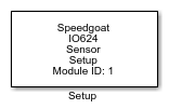
Description
Your model can contain only one Setup block
for each I/O module in your target machine.
All the supported I/O types for this module can be configured in the Setup block
dialog box. This block will therefore have an impact on other driver blocks (Send,
Receive, Sync Status, Sync Pulses and Wheel Speed (WS) Control).
Ports
This driver block has no input or output ports.
Parameters
The nine tabs of the Setup block contain the IO624 I/O module configuration
settings.
Refer to the IO624
main page for the cycle time and bit time specifications, as well as
details about the max time factor mentioned below.
Main Tab
-
Module ID
The Module ID has two functions:
It defines the logical connection between the Setup block and its I/O
blocks
It also informs the auto-search feature of the PCI Slot parameter. If
only one I/O module of this type is installed, the Module ID must be set
to 1. If n modules are installed, it
must be in the range 1:n. Not all the I/O modules installed in the
target machine need to be used. To see how each I/O module maps to a
Module ID, use this Speedgoat API:
speedgoat.getIoInterfaces("TargetName", "mySpeedgoat")
-
PCI Slot (-1: auto-search)
There are two approaches for mapping this block to a specific I/O module installed
in your target machine. All modules of the same type must be configured using the
same method.
Auto-Search: with the default value -1 the I/O module will be automatically located in the
target machine. If you have multiple modules of the same kind, the
Module ID defines which module is associated with this block. To see how
each I/O module maps to a Module ID, use this Speedgoat API:
speedgoat.getIoInterfaces("TargetName", "mySpeedgoat")
Explicit Addressing: to explicitly define the logical address of the
I/O module in the target machine, you can provide the PCI bus and slot
numbers as a vector: [bus, slot]. To determine these numbers, run the
following command in the MATLAB command window:
speedgoat.getIoInterfaces("TargetName", "mySpeedgoat", "Advanced", true)Note
that the PCI address can change whenever an I/O module is added or
removed – usually, auto-search is the best option.
-
Channel X
The IO624 I/O module supports up to eight channels. Each channel can
be disabled or selected as a PSI5, custom, square wave, PWM, or AK/VDA
sensor emulator.
-
Channel Monitor
The module measures the voltage between the VDD and VSS pins. The main
application is for Sync pulse. The channel selected is in the Receive
block.
Channel Tab
- Current Level Settings
These common parameters are used by all Sensor Emulators.
-
Current Settings
Select between Default or Custom for the High, Mid, and
Low current parameters. Default will set the default current
parameter based on the communication protocol selected. Custom enables the configuration parameters.
High, Mid and/or Low
parameters are available depending on the sensor emulator
selected.
-
High [μA]
Defines the high current level in microamperes (0 to 75000).
-
Mid [μA]
Defines the mid current level in microamperes (0 to 75000).
-
Low [μA]
Defines the low current level in microamperes (0 to 75000).
-
Time Base Setting
The time base must be multiplied by the time factor to obtain the
cycle time or the bit time in the configuration. If there is no
indication that the time base is fixed, then these are the
options:
PSI5 Sensor Emulator
These parameters are displayed when PSI5 Sensor
Emulator is selected in the Main tab. All the input and output
signals are controlled by the Send, Receive, Sync Status and Sync Pulses
blocks.
-
Communication Mode
Select between PSI5-A
(Asynchronous), PSI5-U/P
(Synchronous without Daisy Chain), PSI5-D (Synchronous Daisy Chain) and
PSI5-V (Variable Time Triggered
Synchronous) communication mode.
-
Number of Bits
The Number of Data Frame Bits (1 to 32). This value must not include the
Start bits.
-
Start Bit Enable
Select between Start Bit Enable,
Start Bit Disable and Start Bit Custom.
-
Start Bits [S1, S2]
For PSI5 sensor-to-ECU communication, the two start bits are
always coded “0”. You can nonetheless disable this parameter or
define a custom configuration.
-
Default Payload
Defines the default data frame transferred from the sensor to the
ECU. The payload must include the parity or CRC bits. The bits are
transmitted in ascending order, starting with bit 0. The Default Payload is only sent when the
Sensor Send block has no input data. In PSI5-D (Synchronous Daisy
Chain) mode, the default payload is transmitted until the sensor
address is received from the ECU. The default payload length is
32-bit words. Data Type: uint32.
-
Slot Delay [μs]
The delay between the start of a synchronization pulse, and the
data frame (0 to MaxFactor). This delay can be used to determine in
which slot the sensor will send its data.
-
ECU to Sensor Communication
Select between Tooth Gap and
Pulse Width method.
Only synchronization pulses within the permitted time window are
recognized. Refer to the usage notes for more information.
-
ECU Data Frame 2 Length
Select between Frame 2a Long
(Nibble) or Frame 2b Long
(Byte) length according to the expected Frame 2 from
the ECU.
-
Signal Sustain Voltage [mV]
The voltage that is used to detect sync pulses (0 to 26761). Refer
to the usage notes for more information.
- Bit Rate
Select between 125 kbps,
189 kbps, and Custom. Custom enables the Bit Time
Factor parameter.
-
Bit Time Factor
The factor (1 to max time factor) that is
in operation with the respective Time
Base parameter to obtain the bit time in
microseconds.
-
Time Base
Multiplicand of the respective factor. For the PSI5 sensor
emulator, the time base of the bit time is always 0.1 [μs].
-
Cycle Time Factor
The factor (1 to max time factor) that is
in operation with the respective Time
Base parameter to obtain the cycle time in
microseconds.
-
Time Base
Multiplicand of the respective factor. For the PSI5 Sensor, the
Time Scale of the Cycle Time is always 1 [μs].
Square Wave Sensor Emulator
These parameters are displayed when Square Wave Sensor
Emulator is selected in the Main tab. All the input signals are
controlled by the WS Sensor Control Block.
-
Time Base
Multiplicand of the respective factor.
-
Pulse Time Factor
The factor (1 to max time factor) that is
in operation with the respective Time
Base parameter to obtain the pulse time.
-
Time Base
Multiplicand of the respective factor.
-
Cycle Time Factor
The factor (1 to max time factor) that is
in operation with the respective Time
Base parameter to obtain the cycle time.
-
Enable Dynamic Timing
Adds input ports for the Pulse and Cycle Time on the IO624 WS
Sensor Control block. This allows to tune these values during
runtime.
PWM Sensor Emulator
These parameters are displayed when PWM Sensor
Emulator is selected in the Main tab. All the input signals are
controlled by the WS Sensor Control Block.
-
Pulse Time Base
Multiplicand of the respective factor. For the PWM sensor
emulator, the time base of the pulse time is always 0.1 [μs].
-
Pulse Time Factor
The factor (1 to max time factor) that is
in operation with the respective Time
Base parameter to obtain the pulse time.
-
Cycle Time Base
Multiplicand of the respective factor.
-
Cycle Time Factor
The factor (1 to max time factor) that is
in operation with the respective Time
Base parameter to obtain the cycle time.
-
Enable Dynamic Timing
Adds input ports for the Pulse and Cycle Time on the IO624 WS
Sensor Control block. This allows to tune these values during
runtime.
AK / VDA Sensor Emulator
These parameters are displayed when AK / VDA Sensor
Emulator is selected in the Main tab. All the input signals are
controlled by the WS Sensor Control Block.
-
Bit Time Base
Multiplicand of the respective factor. For the AK / VDA sensor
emulator, the time base of the bit time is always 0.1 [μs].
-
Bit Time Factor
The factor (1 to max time factor) that is
in operation with the respective Time
Base parameter to obtain the bit time.
-
Cycle Time Base
Multiplicand of the respective factor.
-
Cycle Time Factor
The factor (1 to max time factor) that is
in operation with the respective Time
Base parameter to obtain the cycle time.
-
Speed Pulse
Defines the encoding start current level (Speed pulse). Select
between Normal (High Current) and
Artificial (Mid
Current).
-
Enable Dynamic Speed Pulse Level
Adds an input port for the Speed Pulse Level (SPLvl) on the IO624
WS Sensor Control block. This allows you to tune the speed pulse
level during runtime.
-
Enable Dynamic Timing
Adds input ports for the Bit and Cycle Time on the IO624 WS Sensor
Control block. This allows to tune these values during
runtime.
Custom Sensor Emulator
These parameters are displayed when Custom Sensor
Emulator is selected in the Main tab. All the input signals are
controlled by the WS Sensor Control Block.
-
Mode
Select between Direct Control,
FIFO-Sequencer, and FIFO-Triggered.
-
Direct Control
Allows to select which current level is active as the default
output channel current.
-
FIFO-Sequencer
Allows to output a frame of current levels, which can hold 16
current-level settings. When a new frame is loaded into the FIFO, it
is automatically output during the next cycle. To output frames
equidistantly, the data must be reloaded after each cycle.
-
FIFO-Triggered
Allows to output frames of current levels every sample time. The
number of frames is defined in FIFO Number of
Frames.
-
FIFO Number of Frames
Defines the number of FIFO frames to be selected; can be from 1 to
16. The full FIFO can hold up to 256 current-level settings
(16x16).
-
Time Base
Multiplicand of the respective factor.
-
Pulse Time Factor
The factor (1 to max time factor) that is
in operation with the respective Time
Base parameter to obtain the pulse time.
-
Time Base
Multiplicand of the respective factor.
-
Cycle Time Factor
The factor (1 to max time factor) that is
in operation with the respective Time
Base parameter to obtain the cycle time.
-
Enable Dynamic Timing
Adds input ports for the bit time on the IO624 WS Sensor Control
driver block. This allows you to tune the values during
runtime.