EnDat - Sniffer v1
EnDat - Sniffer v1 — The EnDat Sniffer code module
is used to monitor the data stream of an existing EnDat data communication.. The
driver block can be configured for generic support of different EnDat encoders.
The driver block is currently only supporting EnDat 2.1
commands
Library
Simulink Real-Time - Speedgoat
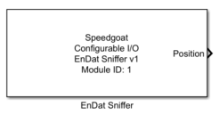
Description
The EnDat Sniffer code module is used to monitor the data stream of an existing
EnDat data communication.. The driver block can be configured for generic support of
different EnDat encoders.
The driver block is currently only supporting EnDat 2.1 commands and can only be
used to sniff the position and revolution value. If particular EnDat 2.2
functionality is required, Speedgoat can provide this upon request.
Ports
This EnDat Sniffer driver block has no inputs, and up to five output ports.
Outputs
-
Position
The encoder position value.
-
Position Width
The number of bits for the position value representation. This port is
only visible if a multiturn-setup is selected (Distinguishable Revolutions Data Width is set different
to 0)
-
Revolution
The encoder revolution value. This port is only visible if a
multiturn-setup is selected (Distinguishable
Revolutions Data Width is set different to 0)
-
Revolution Width
The number of bits for the revolution value representation. This port
is only visible if a multiturn-setup is selected (Distinguishable Revolutions Data Width is set different
to 0)
-
Error Port
The 8 bit error code, decoded as follows:
Parameters
Tab: Module setup
-
Configurable I/O Module ID
This parameter associates a code module block with a configurable I/O module setup
block. Set this value to match the Module ID defined in the setup block of the
required configurable I/O module.
-
Channel Vector
A vector of channels this driver block entity will access. You can specify
channels in the range 1-N (N = the number of channels implemented in your specific
configuration file defined in the Setup block). The width of this vector also
defines the subsequent size of some of the following parameters if scalar expansion
applies. With a single block, all the channels of the block are synchronized.
-
Sample Time
Defines the base sample time at which this driver block gets its sample hit. This
parameter can also be set to -1 for inherited
sample time. The units are in seconds.
Tab: EnDat configuration
-
Position Data Width Vector
Configures the number of data bits for the position reading of the
EnDat encoder. Valid range 1 to 32.
-
Distinguishable Revolutions Data Width Vector (multiturn only)
Configures the number of bits for the distinguishable revolutions
reading of the EnDat encoder. For single-turn encoder a value of 0 needs
to be configured. Valid range 0 to 15.
-
Reset Time Vector [s]
The time until the EnDat Sniffer aborts the reception of an ongoing
EnDat frame in case the CLK singal line stays high for a bigger time
than this parameter (→ CLK signal is inactive).
-
Show Error Port
If checked, the error port is enabled. The error port holds
information of several errors decoded as follows: