EnDat - Decoder v1
EnDat - Decoder v1 — The EnDat code module acts as
the master implementation of the EnDat communication. The driver block can be
configured for generic support of different EnDat
encoders.
Library
Simulink Real-Time - Speedgoat
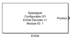
Description
The EnDat decoder that is implemented on the configurable I/O module acts as the
master implementation of the EnDat communication. The driver block can be configured
for generic support of different EnDat encoders. It is fully EnDat 2.2 compatible,
however the driver only uses the minimun needed EnDat 2.1 commands:
The driver uses the EnDat command Enc Send Position
Values to request the position from the EnDat encoder
In case the driver parameter Automatic Detection
of Encoder Data Width is enabled, the driver uses the
EnDat command Select Memory Area and Enc
Send Parameters to read the parameter
Distinguishable revolutions (EnDat Parameter
17, MRS Section A3) and Number of clock pulses for transfer of
the position value (EnDat Parameter 13, MRS Section A1)
to determine the correct number of bits for a proper
communication.
Any other EnDat command is not used by the driver, Speedgoat can
provide more commands upon request.
Ports
This EnDat driver block has no inputs, and up to five output ports.
Outputs
-
Position
The encoder position value.
-
Position Width
The number of bits for the position value representation. This port is
only visible if a multiturn-setup is selected (Distinguishable Revolutions Data Width is set different
to 0) or if Automatic detection of encoder data
width is set
-
Revolution
The encoder revolution value. This port is only visible if a
multiturn-setup is selected (Distinguishable
Revolutions Data Width is set different to 0) or if
Automatic detection of encoder data
width is set
-
Revolution Width
The number of bits for the revolution value representation. This port
is only visible if a multiturn-setup is selected (Distinguishable Revolutions Data Width is set different
to 0) or if Automatic detection of encoder data
width is set
-
Error Port
The 8 bit error code, decoded as follows:
Parameters
Tab: Module Setup
-
Configurable I/O Module ID
This parameter associates a code module block with a configurable I/O module setup
block. Set this value to match the Module ID defined in the setup block of the
required configurable I/O module.
-
Channel Vector
A vector of channels this driver block entity will access. You can specify
channels in the range 1-N (N = the number of channels implemented in your specific
configuration file defined in the Setup block). The width of this vector also
defines the subsequent size of some of the following parameters if scalar expansion
applies. With a single block, all the channels of the block are synchronized.
-
Sample Time
Defines the base sample time at which this driver block gets its sample hit. This
parameter can also be set to -1 for inherited
sample time. The units are in seconds.
Tab: EnDat configuration
-
Automatic Detection of Encoder Data Width
If set, the EnDat driver block will automatically determine the data
width configuration of the encoder by reading out its internal
registers. If not set, the data width configuration can be configured
manually. Note that in this case, Position Data
Width and Distinguishable
Revolutions Data Width must be set correct according to
the connected EnDat Encoder. If that's not the case, the position and/or
the revolution value of the driver output are incorrect and the driver
might cause a timeout error.
-
Position Data Width Vector [bit]
Configures the number of data bits for the position reading of the
EnDat encoder. Valid range 1 to 32.
-
Distinguishable Revolutions Data Width Vector (multiturn only)
Configures the number of bits for the distinguishable revolutions
reading of the EnDat encoder. For single-turn encoder a value of 0 needs
to be configured. Valid range 0 to 15.
-
Transmission Frequency Vector [Hz]
Configures the EnDat transmission frequency.
-
Recovery Time Vector [s]
Configures the recovery time (tst) for start bit recognition. With low
transmission rates (EnDat transmission frequency f_trans < 400kHz)
the same value as 1/Transmission Frequency Vector
[Hz] can be set. With high transmission rates, the
recovery time need to be set much higher than the frequency
factor.
![[Note]](images/note.png) | Note |
|---|
The resolution of the parameters Transmission Frequency Vector [Hz] and Recovery Time Vector [s] depends upon
the FPGA frequency. The effectively applied frequencies and
times are shown in the Effective values |
-
Show Error Port
If checked, the error port is enabled. The error port holds
information of several errors decoded as follows: