EnDat - Encoder v1
EnDat - Encoder v1 — The EnDat Encoder code module
acts as the slave implementation of the EnDat communication. The driver block
can be configured for generic support of different EnDat encoders and
setups.
Library
Simulink Real-Time - Speedgoat
Description
The EnDat encoder that is implemented on the configurable I/O module acts as the
slave implementation of the EnDat communication. The driver block can be configured
for generic support of different EnDat encoders and setups. The implemented encoder
fully supports all EnDat 2.1 and EnDat 2.2 commands, however the driver itself is
only able to set position values and to statically force the F1 error bit. The EnDat
encoder implementation contains a fixed map for all the parameters in the different
memory areas. Speedgoat can provide different memory contents upon request.
Ports
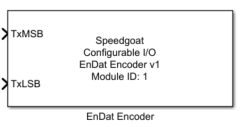
This EnDat Encoder driver block has two inputs and no output ports.
Inputs
-
TxMSB
The upper 32-bit of the data that will be sent upon a position request
from the EnDat master.
-
TxLSB
The lower 32-bit of the data that will be sent upon a positoin request
from the EnDat master.
Parameters
Tab: Module Setup
-
Configurable I/O Module ID
This parameter associates a code module block with a configurable I/O module setup
block. Set this value to match the Module ID defined in the setup block of the
required configurable I/O module.
-
Channel Vector
A vector of channels this driver block entity will access. You can specify
channels in the range 1-N (N = the number of channels implemented in your specific
configuration file defined in the Setup block). The width of this vector also
defines the subsequent size of some of the following parameters if scalar expansion
applies. With a single block, all the channels of the block are synchronized.
-
Sample Time
Defines the base sample time at which this driver block gets its sample hit. This
parameter can also be set to -1 for inherited
sample time. The units are in seconds.
Tab: EnDat configuration
-
Position Data Width Vector [bit]
Configures the number of data bits for the position of the EnDat
encoder. Valid range 1 to 32.
-
Distinguishable Revolutions Data Width Vector (multiturn only)
Configures the number distinguishable revolutions as given by the
datasheet of the EnDat encoder. For single-turn encoder a value of 0
needs to be configured. Valid range 0 to 15.
![[Note]](images/note.png) | Note |
|---|
The Position Data Width and the
Distinguishable Revolutions Data
Width are stored in the encoder to Number
of clock pulses for transfer of the position value
(EnDat Parameter 13, MRS Section A1) and Distinguishable
revolutions (EnDat Parameter 17, MRS Section
A3).
|
-
Recovery Time tm Vector [s]
Configures the recovery time (tm) of the EnDat Encoder.
-
Rearming Time tR Vector [s]
Configures the rearming time (tR) of the EnDat Encoder.
-
Calculation Time tcal Vector [s]
Configures the calculation time (tcal) of the EnDat Encoder.
-
Delay Propagation Time td Vector [s]
Introduces a certain delay on data line to emulate the delay
propagation of a long cable
| Note |
|---|
The resolution of the above described timing- parameters
depends upon the FPGA frequency. The effectively applied times
are shown in the Effective
values |
-
Data Signal FPGA Internally Generated
Uses FPGA internally generated data (counter) for position requests.
The counter increases at every EnDat frame.
-
Force F1 Error Bit
Configures if the F1 error flag is set or not
-
Force CRC Error
Forces a CRC error on the communication (inverts the CRC value)
| Note |
|---|
This parameter is available in EnDat Encoder Driver v1.1 and
subsequent versions. |