IO750 - Setup v2
IO750 - Setup v2 — Configure the IO750 I/O
module
Library
Simulink Real-Time - Speedgoat
Description
The Setup block configures the protocol stack of the related I/O module and
enables the Send and Receive blocks to exchange data on the network.
Ports
This driver block has no input or output ports.
Parameters
Tab: General
- Module ID
The Module ID has two functions:
It logically connects the Setup block and its I/O blocks
It also informs the auto-search feature of the PCI Slot parameter. If only
one I/O module of this family is installed, the Module ID must be set to
1. To see how each I/O module maps to a
Module ID, use this Speedgoat API:
speedgoat.getIoInterfaces("TargetName", "mySpeedgoat")
This Setup block belongs to two families of I/O modules that use the same hardware
for multiple protocols. Across both families, the Module ID must be unique.
IO64X/IO75X (single-node modules): IO641,
IO642, IO643, IO644, IO750, IO751, IO752, IO753, IO754, IO755, IO756,
IO758
IO64X-32/IO75X-32 (multi-node modules):
IO642-32, IO752-32, IO754-32, IO756-32
If the PCI Slot parameter is set to -1
(auto-search), the Module ID must be in the range 1:n, where 'n' cannot be larger
than the number of modules of this type installed in the target machine. Not all
installed I/O modules need to be used.
To use this Setup block with a multi-node I/O module (IO75X-32 family), the Module
ID must be defined as a two-element vector. The second vector element is the
sub-module ID. It describes the specific node (1:32) within the I/O module. The 32
nodes are internally connected to form two linear networks (daisy-chain), where the
first and the last node of both chains are externally accessible. If one node is not
configured (has no Setup block), the chain terminates at this point. The sub-module
IDs must therefore start at node 1, 16, 17 or 32 and not have any gaps.
![[Note]](images/note.png) | Note |
|---|
When using I/O modules of both families simultaneously (single-node and
multi-node I/O modules), always use explicit addressing in the PCI Slot parameter. Ignore the Module IDs returned by
the getIoInterfaces function and instead assign unique Module IDs accross all
modules used. |
-
PCI Slot (-1: auto-search)
There are two approaches for mapping this block to a specific I/O module installed
in your target machine. All modules of the same type must be configured using the
same method.
Auto-Search: with the default value -1 the I/O module will be automatically located in the
target machine. If you have multiple modules of the same kind, the
Module ID defines which module is associated with this block. To see how
each I/O module maps to a Module ID, use this Speedgoat API:
speedgoat.getIoInterfaces("TargetName", "mySpeedgoat")
Explicit Addressing: to explicitly define the logical address of the
I/O module in the target machine, you can provide the PCI bus and slot
numbers as a vector: [bus, slot]. To determine these numbers, run the
following command in the MATLAB command window:
speedgoat.getIoInterfaces("TargetName", "mySpeedgoat", "Advanced", true)Note
that the PCI address can change whenever an I/O module is added or
removed – usually, auto-search is the best option.
Tab: Ethercat
- Bus Start
Automatic: The device starts the communication immediately
after the initialization of the real-time application on the
target. The communication is maintained even if the
real-time application stops.
Application controlled: After initialization of the
real-time application on the target, the communication of
the subordinate device with the network is off. The device
starts the communication immediately after the real-time
application has been started. The device stops the
communication on the network when the real-time application
stops.
- DC Synchronous Mode
This parameter lets you synchonize your model or parts of it to
incoming EtherCAT PDO frames. If checked, you must place the related
IO750 Send and Receive blocks in a function-call subsystem connected to
an Interrupt Setup block. Refer to the Utilities
documentation for more information on this block.
In the Interrupt Setup block, please select the same Module ID as in
the IO750 Setup block. Do not forget to activate Distributed Clocks in your EtherCAT main device
configuration and be aware of the DC timings you adjust there.
- Vendor Name
The name of the vendor of the emulated EtherCAT device. If you do not
want to emulate a real device then leave the default value 'Hilscher'. You will find the specified
vendor name in node <EtherCATInfo><Vendor><Name> of
the exported ESI file.
- Group Name
The name of the ESI device group which the emulated EtherCAT device
belongs to. If you do not want to emulate a real device then leave the
default value 'netX'. You will find the
specified group name in node
<EtherCATInfo><Descriptions><Groups><Group><Name>
of the exported ESI file.
- Type Name
The name of the emulated EtherCAT device. If you do not want to
emulate a real device then leave the default value 'netX'. You will find the specified type name in node
<EtherCATInfo><Descriptions><Groups><Group><Type>
of the exported ESI file.
- Vendor ID
The ID of the vendor of the emulated EtherCAT device. If you do not
want to emulate a real device then leave the default value (0xE0000044).
After the real-time application has been started the vendor ID can be
read by the EtherCAT main device at SDO 0x1018 subindex 1. It is also
part of the SII. You will find the specified vendor ID value in node
<EtherCATInfo><Vendor><Id> of the exported ESI file.
- Product Code
The product code of the emulated EtherCAT device. If you do not want
to emulate a real device then leave the default value (0x00000001).
After the real-time application has been started the product code can be
read by the EtherCAT main device at SDO 0x1018 subindex 2. It is also
part of the SII. You will find the specified product code value in node
<EtherCATInfo><Descriptions><Devices><Device>
<ProductCode> of the exported ESI file.
- Revision Number
The revision number of the emulated EtherCAT device. If you do not
want to emulate a real device then leave the default value (0x00020004).
After the real-time application has been started the revision number can
be read by the EtherCAT main device at SDO 0x1018 subindex 3. It is also
part of the SII. You will find the specified product code value in node
<EtherCATInfo><Descriptions><Devices><Device>
<RevisionNo> of the exported ESI file.
- Serial Number
The serial number of the emulated EtherCAT device. If you do not want
to emulate a real device then leave the default value (0x00000000).
After the real-time application has been started the serial number can
be read by the EtherCAT main device at SDO 0x1018 subindex 4. It is also
part of the SII.
- Station Address Alias
The explicit node address of the subordinate device in the EtherCAT
network. Normally, EtherCAT main devices automatically increment and
assign subordinate device addresses depending on the position of the
subordinate device in the EtherCAT network. Besides, main devices can
activate explicit addressing. In this mode, the main device reads the
address alias from the subordinate device's EEPROM to identify the
device in the network. Refer to the main device configuration manual to
learn how to enable this addressing mode.
The value must range between 0 and 65535. The value must be unique in
the EtherCAT network. If 0, no alias will be written to the EEPROM.
- Device Identification Value
A unique identification value that allows the EtherCAT main device to
clearly identify the subordinate device in the EtherCAT network. During
startup, the EtherCAT main device reads the value from the subordinate
device's EEPROM and compares it with the related identifier in the main
device's IO configuration. This check is optional. Please refer to the
main device configuration manual for more information.
The value must range between 0 and 65535. If 0, no identification
value will be written to the EEPROM.
- Export ESI
Creates an EtherCAT Slave Information (ESI) file according to the
identification parameters and PDO configuration. You usually copy the
file to C:\TwinCAT\3.1\Config\Io\EtherCAT to use it in TwinCAT.
Tab: Rx PDO
- RxPDO Mapping
This table defines the process data objects the subordinate device
receives from the main device. They can be read using the IO750 Receive
block. One PDO consists of one to multiple application objects
(=signals). Use the buttons to add, move or delete rows. Depending on
the table content, a CoE object dictionary will be created during the
initialization of the real-time application on the target. The main
device can read that dictionary in order to check the PDO configuration.
The RxPDO sync manager is always at object 0x1C12. It manages PDO
mapping objects starting at 0x1600 which are linked to application
objects starting at 0x2000.
The length of one PDO must be a multiple
of one byte. Since you can define boolean signals, the Setup block
always fills a bitstream to become a full byte. You cannot see those
padding bits in the PDO table but you have to consider them when valuing
the total byte length of your process data image. Bits will be inserted
in the following cases:
Tab: Tx PDO
- TxPDO Mapping
This table defines the process data objects the subordinate device
sends to the main device. They can be written using the IO750 Send
block. One PDO consists of one to multiple application objects
(=signals). Use the buttons to add, move or delete rows. Depending on
the table content, a CoE object dictionary will be created during the
initialization of the real-time application on the target. The main
device can read that dictionary in order to check the PDO configuration.
The TxPDO sync manager is always at object 0x1C13. It manages PDO
mapping objects starting at 0x1A00 which are linked to application
objects starting at 0x3000.
Byte padding is handle as described in RxPDO mapping.
Tab: SDO
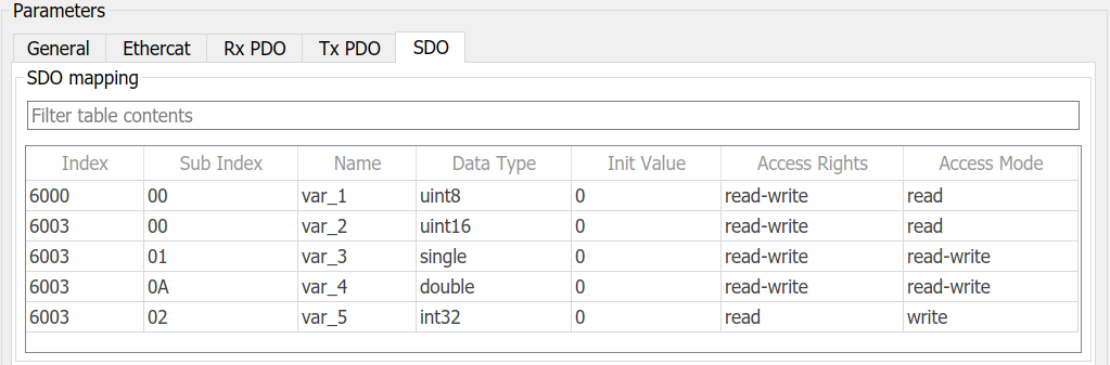
- SDO Mapping
This table defines the service data objects of the subordinate device.
Use the buttons to add, move or delete rows. Depending on the table
content, a CoE object dictionary will be created during the
initialization of the real-time application on the target. The main
device can read and write that dictionary via the EtherCAT protocol. On
the Simulink side, use the SDO Read and Write blocks to read and write
the values of the objects in the dictionary.
An object can either be a simple variable (called VAR in the EtherCAT
specification) or a root object with sub-objects (called RECORD in the
EtherCAT specification). One row of the SDO table is either an object or
a sub-object.
SDO Properties
Enter the Index of the
(sub-) object. The Index
must have 4 digits in hexadecimal format without any leading
or trailing format identifiers. Sub-objects with the same
Index belong to the
same object. Valid values are between 0x0000 and
0xFFFF
Enter the Sub-Index of
the (sub-) object. The Sub-Index must have two digits in
hexadecimal format without any leading or trailing format
identifiers'. A Sub-Index
of 0 determines a row to be an object. A Sub-Index greater than 0
determines a row to be a sub-object. Valid values are
between 0x00 and 0xFF
If only Sub-Index = 0
exists for a given Index
this object will become a simple variable (VAR).
If there are additional Sub-Indices then the row with Sub-Index = 0 will become the
root object (RECORD). In this case the properties Data Type,
Init Value, Access Rights and Access Mode will not be
recognized.
Enter the Name of the
(sub-) object. The Name can
also be read by the main device over EtherCAT
Enter the Data Type of
the (sub-) object. Only fundamental types are supported even
though more data types are defined in the EtherCAT
specification
The Access Rights
determines the permission for an EtherCAT main device when
accessing the (sub-) object.
The Access Mode
determines how to access the (sub-) object from the
real-time application side
Select none
to define the (sub-) object in the dictionary
without reading and writing during runtime
Select read
to read the value of a (sub-) object which has
been written by the EtherCAT main device. The
related output port will then be automatically
added
Select write
to write the value of a (sub-) object which the
EtherCAT main device can then read. The related
input port will then be automatically added
Select read-write to read and write. The SDO
Read and the SDO Write blocks will then
automatically get one more port each
![[Caution]](images/caution.png) | Caution |
|---|
Please consider the following limitations: On IO750 the total amount of process data is limited to 512 bytes (RX
+ TX) The number of PDOs is limited to 254 in each direction The number of application objects (signals) per PDO is limited to 200
The total number of application objects (signals) is limited to 1024
in each direction The total number of SDOs is limited to 4096
|