IO116 - Setup
IO116 - Setup —
Configure the IO116 input/output blocks
Library
Simulink Real-Time - Speedgoat
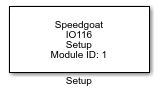
Description
Your model can contain only one Setup block
for each I/O module in your target machine.
All the supported I/O types for this module can be configured in the Setup block
dialog box. This block will therefore have an impact on all the other driver blocks
(Analog input, Analog output, Digital input and Digital output).
Ports
This driver block has no input or output ports.
Parameters
The five tabs of the Setup block mask contain the IO116 I/O module configuration
settings.
Module Setup Tab
-
Module ID
The Module ID has two functions:
It defines the logical connection between the Setup block and its I/O
blocks
It also informs the auto-search feature of the PCI Slot parameter. If
only one I/O module of this type is installed, the Module ID must be set
to 1. If n modules are installed, it
must be in the range 1:n. Not all the I/O modules installed in the
target machine need to be used. To see how each I/O module maps to a
Module ID, use this Speedgoat API:
speedgoat.getIoInterfaces("TargetName", "mySpeedgoat")
-
Analog Voltage Range
Analog voltage range used for the analog input and output channels.
The range is the same for both inputs and outputs.
-
Analog Current Range
Analog current range used for the analog input and output channels.
The range is the same for both inputs and outputs.
-
Autocalibrate
Check this box if the module should calibrate itself the next time
this model (target application) is downloaded and initialized. The
autocalibration function compensates for component aging, and minimizes
the effects of temperature on accuracy. We recommend keeping this
enabled. The calibration normally takes approximately 2 seconds, so we
recommend increasing the host-target communication time-out in the model
configuration parameters to allow for this. The status of the
calibration is displayed on the target screen. The calibration is not
re-executed during normal start/stop operation once the target
application has been downloaded. All input channels are calibrated to a
single internal voltage reference. Offset and gain error corrections for
each channel are determined during the autocalibration process, and are
applied to each channel in real-time during data acquisition.
![[Warning]](images/warning.png) | Warning |
|---|
During the calibration process various signals may be present
at the output pins. These will nonetheless remain within the
configured voltage range. |
-
PCI Slot (-1: auto-search)
There are two approaches for mapping this block to a specific I/O module installed
in your target machine. All modules of the same type must be configured using the
same method.
Auto-Search: with the default value -1 the I/O module will be automatically located in the
target machine. If you have multiple modules of the same kind, the
Module ID defines which module is associated with this block. To see how
each I/O module maps to a Module ID, use this Speedgoat API:
speedgoat.getIoInterfaces("TargetName", "mySpeedgoat")
Explicit Addressing: to explicitly define the logical address of the
I/O module in the target machine, you can provide the PCI bus and slot
numbers as a vector: [bus, slot]. To determine these numbers, run the
following command in the MATLAB command window:
speedgoat.getIoInterfaces("TargetName", "mySpeedgoat", "Advanced", true)Note
that the PCI address can change whenever an I/O module is added or
removed – usually, auto-search is the best option.
Analog Inputs Tab
-
Current Transceiver
This parameter specifies if the input channels are to be used as
current or voltage inputs. If "off" is selected, then the channels will
be configured as voltage inputs. If "on" is selected, then the channels
will be configured as current inputs. In this case the voltage range of
both inputs and outputs is forced to 0 to +5 V and Input Coupling
is set to differential mode regardless of the values selected.
-
Voltage Channels/Current Channels
The name of this parameter changes depending on the value of Current
Transceiver. It specifies the number of voltage/current channels that
will be used.
-
Input Coupling
Either differential or single-ended for 8 differential or 16
single-ended channels. Note that single-ended channels can only be used
if Current Transceiver is set to "off".
Analog Outputs Tab
-
Enable Current Output
Analog current outputs ("Analog Current OUT01" to "Analog Current
OUT04") are enabled when this parameter is checked. In this case the
voltage outputs are not disabled: they are set to a range of 0-5 V.
The output voltage is scaled according to the current outputs; for
example, if the range is set to 4-20 mA, then a value of 0.004 will
cause the I/O module to output 4 mA and 0 V, a value of 0.012
will output 12 mA and 2.5 V, and a value of 0.020 will output
20 mA and 5 V.
-
Enable Alarm Output
This parameter is only available if the Enable Current Output
parameter is active. When checked, the Analog output block displays
"Alarm" ports. The output of these ports will be "1" if an open/floating
line is detected (for example, if the connection to the device is
interrupted/broken).
-
Channel Vector
Values between 1 and 4 in a vector. This driver allows individual D/A
channels to be selected in any order. The number of elements defines the
number of D/A channels used. For example, to use two of the analog
output channels, enter "[1,2]". Number the channels beginning with 1,
even if the board manufacturer starts with 0.
-
Reset Vector
This field specifies the behavior of the channel at model termination.
Enter a scalar or a vector of the same length as the total number of
channels (e.g. "[1 1 1 1]"), even if not all the channels are used. If a
scalar value is specified, its value will be used for all channels. A
value of 1 causes the corresponding channel to be reset to the value
specified in the Initial Value Vector field. A value of 0 causes the
channel to remain at the last value used while the model was
running.
-
Initial Value Vector
This field specifies the initial voltage values for the output
channels. Enter a scalar or a vector of the same length as the total
number of channels (e.g. "[1 1 1 1]"), even if not all the channels are
used. If a scalar value is specified, its value will be used for all
channels. The channels are set to the initial values between the time
the model is downloaded and the time it is started.
Digital Inputs Tab
-
Channel Vector
Values between 1 and 8 in a vector. This driver allows individual
digital channels to be selected in any order. The number of elements
defines the number of digital channels used. For example, to use two of
the digital input channels, enter "[1,2]". Number the channels beginning
with 1, even if the board manufacturer starts with 0.
Digital Outputs Tab
-
Channel Vector
Values between 1 and 8 in a vector. This driver allows individual
digital channels to be selected in any order. The number of elements
defines the number of digital channels used. For example, to use two of
the digital input channels, enter "[1,2]". Number the channels beginning
with 1, even if the board manufacturer starts with 0.
-
Reset Vector
This field specifies the behavior of the channel at model termination.
Enter a scalar or a vector of the same length as the total number of
channels (e.g. "[1 1 1 1]"), even if not all the channels are used. If a
scalar value is specified, its value will be used for all channels. A
value of 1 causes the corresponding channel to be reset to the value
specified in the Initial Value Vector field. A value of 0 causes the
channel to remain at the last value used while the model was
running.
-
Initial Value Vector
This field specifies the initial voltage values for the output
channels. Enter a scalar or a vector of the same length as the total
number of channels (e.g. "[1 1 1 1]"), even if not all the channels are
used. If a scalar value is specified, its value will be used for all
channels. The channels are set to the initial values between the time
the model is downloaded and the time it is started.