IO106 - Setup
IO106 - Setup —
Configure the IO106 input/output blocks
Library
Simulink Real-Time - Speedgoat
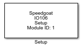
Description
All the supported I/O types for this module can be configured in the Setup block
dialog box. This block will therefore have an impact on the other driver blocks
(Analog input, Start conversion and Read channels). The Analog input (DMA) block is
an exception as it does not use the Setup block.
Ports
This driver block has no input or output ports.
Parameters
-
Parameter Group
This control selects the displayed configuration section, the
parameters of which are then shown in the dialog box below the
"Parameter Group" field. The groups available are:
Module setup
Analog input setup
Parameter Group: Module setup
-
Module ID
The Module ID has two functions:
It defines the logical connection between the Setup block and its I/O
blocks
It also informs the auto-search feature of the PCI Slot parameter. If
only one I/O module of this type is installed, the Module ID must be set
to 1. If n modules are installed, it
must be in the range 1:n. Not all the I/O modules installed in the
target machine need to be used. To see how each I/O module maps to a
Module ID, use this Speedgoat API:
speedgoat.getIoInterfaces("TargetName", "mySpeedgoat")
-
Autocalibration
The autocalibration is enabled by default to obtain maximum
measurement accuracy. The autocalibration function compensates for
component aging and minimizes the effects of temperature on accuracy.
The calibration normally takes approximately 2 seconds, so we recommend
increasing the host-target communication time-out in the model
configuration parameters to allow for this. The calibration is not
re-executed during normal start/stop operation once the target
application has been downloaded. All input channels are calibrated to a
single internal voltage reference. Offset and gain error corrections for
each channel are determined during the autocalibration process and are
applied to each channel in real-time during data acquisition.
Warning: Disabling the autocalibration may cause
the wrong values when the input range is changed.
-
Inter-Module Synchronization
Select either Initiator (default) or Target. If Initiator is selected,
A/D conversions are initiated by this module and the module outputs a
pulse train to optionally trigger other IO106 I/O modules where
"Inter-Module Synchronization" is set to Target. The pulse train is sent
on the I/O connector SYNC I/O pin. Ground is on the SYNC RTN pin (see
the I/O pin mapping section for pin numbers).
If your target machine contains a single IO106 I/O module, then
Initiator must be selected. If Target is selected, the module itself
does not start its A/D conversions, but instead triggers them using a
pulse train from another IO106 I/O module where "Inter-Module
Synchronization" is set to Initiator. The pulse train is received on the
SYNC I/O pin (ground is on the SYNC RTN pin). With this setting, there
must be at least one other IO106 I/O module present with "Inter-Module
Synchronization" set to Initiator, and the modules' SYNC I/O and SYNC
RTN pins must be physically wired together (SYNC I/O to SYNC I/O, SYNC
RTN to SYNC RTN). To use this feature with more than two IO106 I/O
modules, all SYNC I/O pins and all SYNC RTN pins must be wired together
(see the I/O pin mapping section for pin numbers). Exactly one IO106 I/O
module must be set to Initiator and all others to Target.
When using the "Inter-Module Synchronization" setting, the initiator
must use the Start Conversion driver block, and the target the Read
Channels driver block. Otherwise, with a single module, use the Analog
input driver block to read the channels.
![[Note]](images/note.png) | Note |
|---|
DMA cannot be used with inter-module synchronization. |
-
PCI Slot (-1: auto-search)
There are two approaches for mapping this block to a specific I/O module installed
in your target machine. All modules of the same type must be configured using the
same method.
Auto-Search: with the default value -1 the I/O module will be automatically located in the
target machine. If you have multiple modules of the same kind, the
Module ID defines which module is associated with this block. To see how
each I/O module maps to a Module ID, use this Speedgoat API:
speedgoat.getIoInterfaces("TargetName", "mySpeedgoat")
Explicit Addressing: to explicitly define the logical address of the
I/O module in the target machine, you can provide the PCI bus and slot
numbers as a vector: [bus, slot]. To determine these numbers, run the
following command in the MATLAB command window:
speedgoat.getIoInterfaces("TargetName", "mySpeedgoat", "Advanced", true)Note
that the PCI address can change whenever an I/O module is added or
removed – usually, auto-search is the best option.
Parameter Group: Analog input setup
-
Number of Channels
The number of channels to read. This parameter is a scalar value and
must be a multiple of 2. The IO106 I/O module has 32 input channels in
single-ended mode (see "Input Coupling" field below), 31 (30) input
channels in pseudo-differential mode, and 16 channels in differential
mode. This field is restricted to multiples of 2 because the IO106 I/O
module returns two channels with each read of the analog input data
FIFO. If you, for example, want to acquire 13 channels, define the
"Number of Channels" as 14 and ignore the last channel (14) in your
model. In single-ended and differential input coupling mode, the first
channel returned by either the Analog input or the Read Channels driver
block is always channel 1 (or 0 according to the IO106 reference
manual), and the last channel is always the n'th channel based on the
"Number of Channels" setting. In pseudo-differential input coupling
mode, channel 1 is used as a common reference for all other input
channels and its value is of no interest. Therefore, when in this mode,
the Analog input and Read Channels driver blocks only output channels 2
to n.
-
Range
The input range for all A/D channels. This driver does not allow
different ranges for individual channels.
-
Input Coupling
Either Single-ended, Pseudo-differential or Differential. The same
setting applies to all input channels. For more information see the
"Number of Channels" field above, and the IO106 reference manual.
Single-ended: For single-ended channels, each input signal
is measured with respect to the common input return. That
is, each channel reports the difference between the input
signal voltage and the voltage present on the common input
return. This configuration provides the maximum number of
input channels, but allows noise and other forms of
interference on the common return line to appear in the
signal measurement
Pseudo-differential: In this mode the first channel is
designated as the reference for all other channels, and its
sampled value is subtracted from the sampled values of all
other channels. With this arrangement, noise and
interference on the common return line is essentially
canceled, and the first input line can be used as a "remote
sense" line for channels 1 to 31
Differential: Each input channel has a dedicated
associated reference level channel