IO106 - Analog input
IO106 - Analog input —
Reads the IO106 analog inputs
Library
Simulink Real-Time - Speedgoat
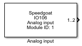
Description
This is the default driver block for acquiring analog input channels from the
IO106 I/O module. This driver block combines the conversion start and channel read
functionality into one block. If you want to separate the start conversion and
channel read functionality in your model (as for multi-board synchronized
acquisition) then use the Start Conversion and Read Channels driver blocks
instead.
Ports
This driver block has one output port returning the acquired analog input channels
(see the "Number of Channels" parameter in the "Setup" dialog box).
As this I/O module has a high channel count, it was decided against returning each
analog input channel via a separate output port in order to not make the driver
block icon use up too much real-estate in the model window.
The single output port therefore returns a vector with the number of elements
defined in the "Number of Channels" field (except for the Pseudo-differential input
coupling mode; see below). Each element is of type double and outputs the acquired
channel value in volts depending on the "Range" setting. The Demux or Selection
block from the Simulink library can be used to access individual elements (channels)
in your model.
For single-ended and differential modes the first element is channel 1 and the
last channel is defined by the "Number of Channels" setting in the corresponding
Setup driver block.
For pseudo-differential mode the first element is channel 2 and the last channel
is defined by the "Number of Channels" setting in the corresponding Setup driver
block.
Outputs
-
1..X (X is the last channel and is defined by the "Number of
Channels" setting in the module's "Setup" block dialog box)
A vector with n elements (where n is the number of selected analog
input channels). Each element corresponds to the value from an A/D
channel in volts. This port is enabled if the "Input Coupling" parameter
in the module's "Setup" block dialog box is set to Single-ended or
Differential.
-
2..X (X is the last channel and is defined by the "Number of
Channels" setting in the module's "Setup" block dialog box)
A vector with n elements (where n is the number of selected analog
input channels). Each element corresponds to the value from an A/D
channel in volts. This port is enabled if the "Input Coupling" parameter
in the module's "Setup" block dialog box is set to
Pseudo-differential.
Parameters
The configuration details are all defined in the setup block.
-
Module ID
This ID defines the link to the corresponding Setup block
-
Sample Time
Defines the base sample time at which this driver block gets its sample hit. This
parameter can also be set to -1 for inherited
sample time. The units are in seconds.