ARINC 825 - Read
ARINC 825 - Read — Receive CAN
messages
Library
Simulink Real-Time - Speedgoat
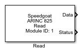
Description
This block receives the specified CAN message(s) from the bus. Multiple blocks can
be used per channel.
Ports
Inputs
- Enable
Enable/Disable message reception.
Outputs
-
Data
Received CAN(-FD) message(s).
CAN-FD message:
Protocol Mode: 1 if a CAN-FD message was received
otherwise 0
Extended: Always 1 (29-Bit ID)
Length: Number of data bytes
Remote: Not used
Error: Not used
BRS: Bit Rate Switch is 0 if data is received with the
nominal baud rate otherwise 1 (Only valid for CAN-FD
messages)
ESI: Error State Indicator is 0 if error state is active
otherwise 1, if error state is passive (Only valid for
CAN-FD messages)
DLC: Data Length Code (Only valid for CAN-FD
messages)
ID: Message ID
Timestamp: Time of message reception
![[Note]](images/note.png) | Note |
|---|
Timestamp resolution 12.5 ns |
Data: Payload data vector
-
Status
Status vector for every message received indicating if the specified
message was received.
Parameters
-
Module Type
Select the type of your I/O Module installed in your target
machine.
-
Module ID
This ID defines the link to the corresponding Setup block
-
Channel
Select the channel to which this driver block corresponds.
-
Message ID
Specify the 29-bit ID of the message(s) which should be
received.
-
Sample Time
Defines the base sample time at which this driver block gets its sample hit. This
parameter can also be set to -1 for inherited
sample time. The units are in seconds.
-
Show Enable Input
Select whether the enable input is active. Otherwise message reception
is always enabled.
-
Show Status Output
Select whether the status output is active.