SSI - Sniffer
SSI - Sniffer — The SSI Sniffer driver block
monitors an existing SSI communication between master and slave and obtains the
data value and the number of bits transmitted per
transaction.
Library
Simulink Real-Time - Speedgoat
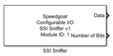
Description
The SSI Sniffer driver block monitors an existing SSI communication between master
and slave.
Ports
The SSI Sniffer driver block has two output ports and no input ports.
Outputs
-
data
The data value monitored on the SSI transaction.
-
Number of Bits
The detected number of bits of the SSI transaction.
- Number of Bits Error
A logical one on this output signals that more than 32 bits or 64 bits
(from version v1.5 and later) of data have been received (only visible
if the Show Number of Bits Error
parameter is checked).
- SCK Frequency
The output displays the clock frequency of the previous received
message in Hz. (Only visible if the option "Show SCK Frequency" is
checked)
- SSI2
A logical one on this outputs signals that the previous received
message was in the SSI2 format. If this is the case, the bit order of
the data are automatically swapped. (Only visible if the option "Show
SSI2" is checked)
Parameters
Tab: Module setup
-
Configurable I/O Module ID
This parameter associates a code module block with a configurable I/O module setup
block. Set this value to match the Module ID defined in the setup block of the
required configurable I/O module.
-
Channel Vector
A vector of channels this driver block entity will access. You can specify
channels in the range 1-N (N = the number of channels implemented in your specific
configuration file defined in the Setup block). The width of this vector also
defines the subsequent size of some of the following parameters if scalar expansion
applies. With a single block, all the channels of the block are synchronized.
-
Sample Time
Defines the base sample time at which this driver block gets its sample hit. This
parameter can also be set to -1 for inherited
sample time. The units are in seconds.
Tab: SSIS configuration
-
Decoding
Determines whether the data is binary or gray decoded.
-
Line Delay Compensation
Delays the clock line by a specific number of FPGA ticks. Use this to
adjust the setup and hold time of the data line time to achieve higher
frequencies. Range 0 to 255.
Tab: Output port configuration
-
Show Data
When this parameter is checked the output to read the received data is
available.
-
Show Number of Bits
When this parameter is checked the output to read the number of
received bits is available.
-
Show Number of Bits Error
When this parameter is checked an additional output is available to
signal that the master is sending more than the supported 32 or 64 (v1.5
and later) clocks per message. The parameter is only visible if the
configuration file supports SSI Sniffer v1.2.
-
Show SCK Frequency
When this parameter is checked an additional output is available to
read the clock frequency. The parameter is only visible if the
configuration file supports SSI Sniffer v1.2.
-
Show SSI2
When this parameter is checked an additional output is available to
signal that the master is expecting data in the SSI2 format. The
parameter is only visible if the configuration file supports SSI Sniffer
v1.2.
![[Note]](images/note.png) | Note |
|---|
From version v1.5 and later, the output data type is uint64. This is
considered a fixpoint data type by Simulink and cannot be interpreted by the
scope block. Either use the data conversion block or view the output data in the
data inspector. |