SSI - Slave v2
SSI - Slave v2 — The SSI Slave driver block
configures the data that will be sent to a SSI Master device when
required.
Library
Simulink Real-Time - Speedgoat
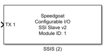
Description
The SSI Slave driver block configures the data that will be sent to a SSI Master
device when required.
Ports
This driver has a number of input ports corresponding to the number of active
channels.
The input ports provide the value to be sent by the SSI Slave to the driver block.
Parameters
Tab: Module setup
-
Configurable I/O Module ID
This parameter associates a code module block with a configurable I/O module setup
block. Set this value to match the Module ID defined in the setup block of the
required configurable I/O module.
-
Channel Vector
A vector of channels this driver block entity will access. You can specify
channels in the range 1-N (N = the number of channels implemented in your specific
configuration file defined in the Setup block). The width of this vector also
defines the subsequent size of some of the following parameters if scalar expansion
applies. With a single block, all the channels of the block are synchronized.
-
Sample Time
Defines the base sample time at which this driver block gets its sample hit. This
parameter can also be set to -1 for inherited
sample time. The units are in seconds.
Tab: SSIS configuration
-
Coding
Whether the output signal is coded in Binary or Gray code
-
Data Size
The total number of bits used in the transmission units are in the
range [1 to 32] bits, or [1 to 64] bits from version v2.5 and
later.
-
Transfer Timeout
The length of the delay Tm (see Timing Diagram) in
seconds.
-
Clock Timeout
The timeout to abort the current communication in case insufficient
master clock cycles are received for the defined data length ('Word
size' vector parameter) in seconds.
-
SSI2 Coding
Check this box if the SSI Slave module will be used to write an SSI2
decoder. In this case the MSB and LSB of the output frame are reversed
compared to a standard SSI encoder.
![[Note]](images/note.png) | Note |
|---|
The FPGA clock frequency and the corresponding time of a tick can be found in the
Setup block. |
| Note |
|---|
Values expressed in seconds will be rounded to the FPGA resolution. For
instance, if FPGA base clock is equal to 75[MHz], then the resolution is
13.33[ns]. |